
|
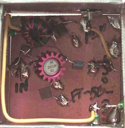
Input is right above where "In" is written on the board at the middle left. Output is at the middle right, which goes to the MRF472 pair. The optional output is at the top right of the image, an orange wire is seen going from the output of the amplifier to the jack. 12 Volts is routed through the feedthrough capacitors. |
|
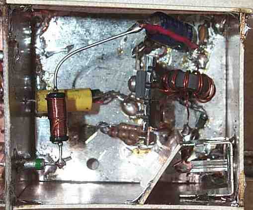
The two MRF472s are mounted back to back, beside each other, on the heatsink. The round yellow object is a rather large .068 capacitor, which is the input to the final amplifier. The RF wire-wound choke is half-way hidden beneath the capacitor. The output is the jack at the bottom right of the image, and is shielded with a small piece of PCB to prevent feedback to the input of the amplifier. The heatsink was originally a TO-3 transistor heatsink, hammered flat and holes drilled to accept the MRF472s. This allows the collectors of the transistors to be next to each other, the pins bent up, soldered together, and connected to the output transformer. The emitter resistors are soldered to the pins on each end of the heat sink. The bypass capacitors are at the top of the image, connected to the RF Choke, then to the output transformer. |
|
|
Send E-Mail || Amateur Radio Receivers || CW Transmitter w/Superhet Receivers