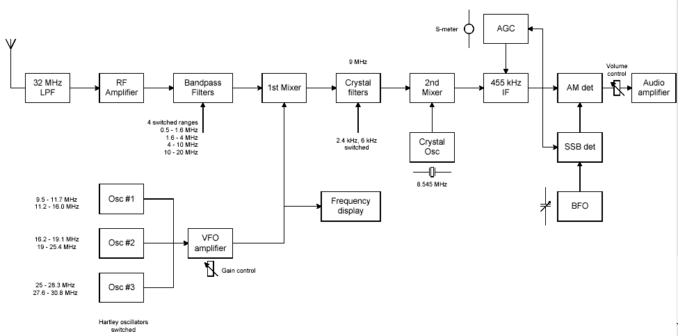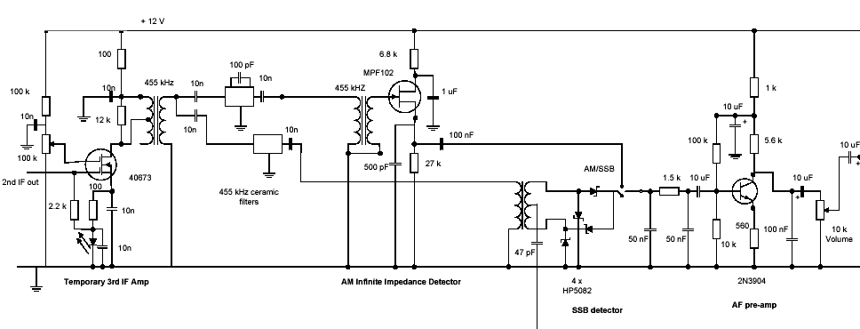


Download the Electroluminescent.pdf file for complete circuit details.
|
The first attempt at an AM detector for the receiver was Duncan's as documented in the following quote from his email: "3. Disconnect the BFO and put in a simple diode at the end of the IF strip (before the 455 kHz ceramic filter). "Works reasonably well, but there is some problem with the AGC action. What I noticed is that there wasn't enough audio volume, and the output was a little distorted. I connected the diode detector to the output of board 1, and apart from lack of gain, the signal sounded okay. "If I disconnect the AGC line and connect it to a 0 - 6 Volt pot, I can set the gain so that there is background noise between signals (though the receiver is really quiet!), and set the gain to give good undistorted volume when tuned in to an AM station. "When the AGC line is connected to the AGC circuitry, the audio that comes out is low volume and sounds compressed and distorted. The AGC action does not seem to be right. I haven't had a chance to work out what is going on yet - have you used the receiver with AM stations much? "It is as though the voltage drops too quickly when tuning in to a station, but won't drop off far enough on really strong stations." |
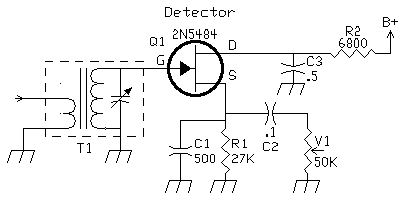
Then Success This schematic is redrawn from the 1988 ARRL Handbook, page 18.11, Fig. 20, Chapter 18, Voice Communications. "David - I'm pleased to report that an Infinite Impedance Detector, as per attached circuit (from ARRL handbook) gives very good results. I used an MPF102, with the input to a 455 kHz IF coming from the output of the 455 kHz ceramic filter (the BFO circuitry completely out of circuit at this stage of testing). "The output (without the 50K gain control) going to the 1.5K resistor (R60). Works very well. I've been tuning across the 9 MHz - 10 MHz band and SW reception is quite good. "The next problem is bandwidth for AM. I've removed two of the 4 MHz crystals and that is better, but for proper AM reception really need a 5 kHz wide filter with steep sides. "I'm still deciding what to do here, and how to get good SW coverage. Currently I have the VFO frequency varying from about 12 - 14 MHz, and stability seems very good." |

|
"One note, I have been finalising the arrangement with switching the BFO and AM detector (I'm still using the IID circuit), and I feel that just a little more gain is required at the end of the IF stage - I'm experimenting with a 3rd MOSFET, set for minimal gain. "I don't have much in the way of test instruments, so I'm doing this by "ear" and "feel", but want about another 6 dB of gain, really just to make up for the loss through the final ceramic filter. "My current arrangement has a 3rd MOSFET with minimal gain, feeding two ceramic filters (one to BFO and one to AM detector), and the arrangement seems to work well. It all looks a bit mickey-mouse tacked on the top with a few wires, but I'll clean it up later." Audio"I've ripped out the 2N3904 transistor pre-amp, and replaced it with a simple Op Amp, using the ubiquitous 741! There was always something funny about the pre-amp. "It never worked for me properly with any capacity value in the emitter bypass position, and seemed to have a bassy response. The simple Op Amp with a gain of about 6 is slightly more than required (probably something around 4 would be better). "All the bassy noise and instability has gone. I've also used a couple of the relays that you sent me to do the AM/SSB switching. This works well (haven't tried LEDs in the BFO detector yet). "I've used the same LPF filter you used, and reduced the coupling capacitors to give some HPF action. Audio now sounds good and is quite stable." |
|
|
Send E-Mail || Amateur Radio Receivers || Electroluminescent Receiver || Duncan Watson's SWL Receiver || Gary Rondeau's SWL Receiver Modifications
