
| One of the main problems with the original LED MOSFET design was that the first design post mixer amplifier, a single MOSFET amplifier, would always cause trouble with oscillations. With the help of an HP spectrum analyzer and a lot of experimenting, I came up with using a single balanced amplifier as the post amplifier. Looking at a circuit on Page 15.31, top of figure 15.45, in the 2000 ARRL Handbook for Radio Amateurs, inspired an idea on how to mate them. |
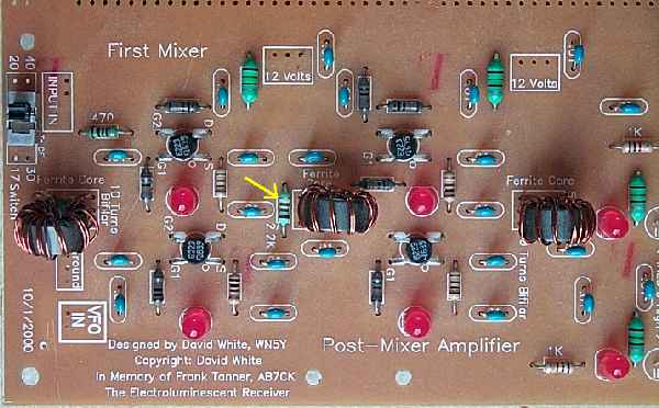
| The T4-6T's were replaced with ferrite cores, FT50A-75, wound with a 10 turn bifilar winding and a secondary of 5 turns. The middle transformer was wound with only the bifilar winding. The ferrite cores gave 8dB more gain over the T4-6T's. |
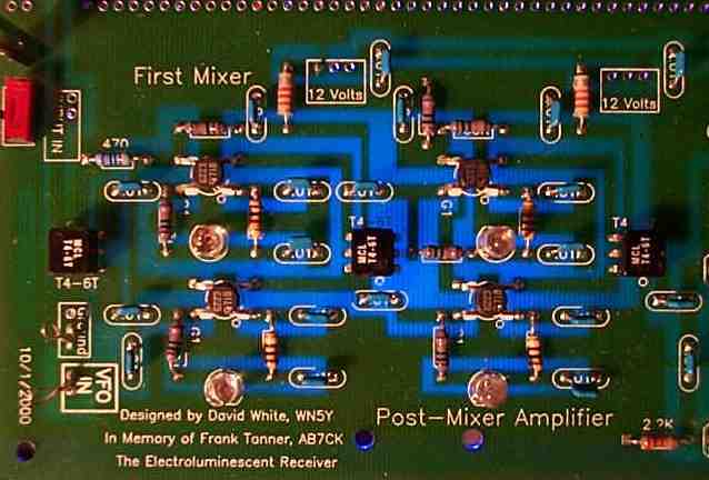
The Single Balanced Mixer/Single Balanced Amplifier Combination DiscoveryThe main problem of the oscillations was the strong VFO energy (6 volts peak to peak, or +7dBm) going through the mixer to the input of a single MOSFET post amplifier. The VFO signal, combined with the second and third harmonic signals, would drive the amplifier to oscillate. I had tried using the MOSFET single balanced amplifier as the post mixer amplifier, but the excessive use of transformers kept me from seriously considering it. Both the mixer and the amplifier has a 1:4 at the input and output, and putting them together would put two transformers in a row. While looking at the two sitting in a row, I pondered how this might be made into a quad mixer. This could eliminate the transformers between the circuits. I looked in the 2000 ARRL Handbook and came across Colin Horrabin's, G3SBI, quad FET mixer. After looking at how he used his transformers, I came up with the idea of tying the single balanced amplifier into the input leads of the output transformer of the mixer. This worked great. It was solid as a rock. Never could get it to oscillate, even with my signal generator in overdrive. The capacitors (.01s) on either side of the middle transformer are the coupling capacitors to the amplifier. They go to Gate 1, with a 100K resistor to ground. G1 is marked on the mixer and amplifier MOSFETs. In probing the circuit with an SA, the mixer and amplifier seemed to work as one unit. Any measurements between the mixer and amplifier were never completely trustworthy. The gain measured at the output of the mixer would be the same gain at the output of the amplifier. But when the two were disconnected, the gain of the mixer would be 10 dB less. The single balanced MOSFET amplifier can handle the excessive VFO energy from the mixer without oscillating and provides 7db of gain. |
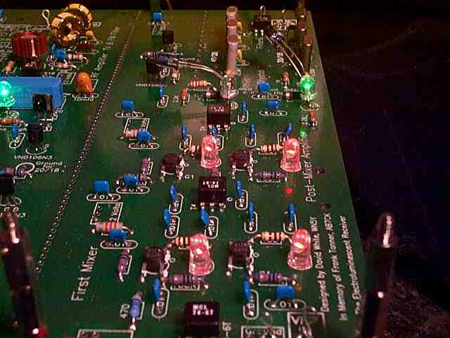
| In the picture above, the first mixer, post mixer amplifier and crystal filter are shown. This is the most intense area for LEDs, with 8 in a short space. Six LEDs and two IR LEDs. The combination mixer-amplifier gives about 14dB of gain, which is needed to overcome crystal losses, convert through the second mixer (with a little gain here) and provide enough signal to mask the noise of the 455kHz IF strip. If the S-meter is carefully adjusted, static crashes (band noise) will be moving the S-meter, activating the AGC. Tuning the bandpass control, the S-meter will rise when a band is tuned in. |
|
There has been a change in the application of the RF chokes for bypassing the 12 volts on the First Mixer/Post-Amplifier. RF Chokes were originally used because SA analysis showed leakage of frequencies from the mixer/amplifier was less on the 12 volt line with the RF Chokes than 100 ohm resistors. But some problems with oscillations in the mixer/amplifier left the issue open to more thought. RF Chokes have many problems with their resonate frequency causing problems in receivers. Unless the inductance of the chokes are measured and applied to the stray capacitance of the circuits you never know what frequencies they might oscillate. Considerable talk of this problem on the EMRFD site led to my conclusion that a minimum of RF Chokes should be used in a receiver. There have been unknown oscillations below the 40 meter band usually occuring with strong SWL signals leaking into the receiver bandpass filters. Speculation also centered on some regeneration occuring between the input and output of the mixer/amplifier combination. After the talk of RF Chokes being such problem makers with stray oscillations, the point of interest of these problems began to center on the use of the RF Chokes feeding the mixer and mixer amplifier. This seemed the perfect place for them to be causing unwanted oscillations, especially with all the high level signals and many harmonics that this mixer/amplifier has floating around. So the RF Chokes were pulled and replaced with 100 ohm resistors. Both receivers had the 470 ohm resistor between the ends of the bifilar core between the mixer and amplifier which was the fix for the oscillation problems. No difference was noted in the performance of the receiver. But I found a quote on the internet from Wes Hayward on the design of MOSFET amplifiers: The other resistor is one that is right in series with the drain. This is often in the region of 20 to 100 Ohms. This serves to provide a wideband load that kills UHF oscillations. The utility of this resistor can be studied with a microwave stability analysis, easily done with numerous programs, or from scratch if you are willing to do some analysis. You will see examples of the small drain R in some of the amplifiers in emrfd. UHF oscillations is another problem well documented with MOSFET amplifiers. So this statement combined with speculation with other oscillations brought the issue to a tipping point. The RF Chokes were pulled and 100 ohm resistors put in their place. In all future ELR boards the 100 ohm resistors will be used. I don't have the equipment or software to drill down the problem, but I do know that it is worthwhile to take advice from knowledgeable experimenters. So I would recommend that you take the RF Chokes out of the Mixer and post-mixer Amplifier and replace them with 100 ohm resistors. Probably not a huge problem since the receiver works quite well as is, but for perfection in the mixer well worth doing.
|
Board 1 || VFO || TV & FM, BC Filters || RF Amplifier || Bandpass Filters || First Mixer & Amplifier || Crystal Filter
Send E-Mail || Amateur Radio Receivers || Electroluminescent Receiver
