
| The audio pre-amplifier is patterned after the excellent web pages of N1HFX. N1HFX has excellent tutorials on audio amplifier design. His idea of not including an emitter bypass to stabilize an audio amplifier circuit and including it as a gain booster was incorporated into this circuit. |
|
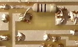
The "Gain Adjust" cap adjusts the gain of the audio pre-amplifier. Dan, WA8YYE, suggested the best value for the gain adjust resistor is a 100 ohm resistor in series with the 2.2mfd electrolytic. See schematic above. The original resistor was 470 ohms and the footprint for the part has that value, but a change to 100 ohm gave the circuit additional gain. If you have a Board 2 built before 7/11/2020, you will need to change the resistor from 470 to 100 ohms. See picture below, resistor is right above the text "2N3904". 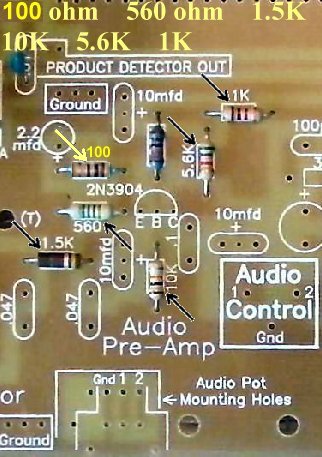 Two capacitor values were changed. The .1 mfd capacitor in the Pre-Audio Amplifier is changed to a .047 capacitor to help with the bandwidth of the amplifier. The 2.2mfd below the Audio Amplifier IC is changed to a 100mfd to keep the audio from clipping at medium to high volume. |
|
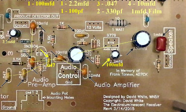
The input power resistor to the amplifier, a 10 ohm, 1 Watt resistor is lowered in value to provide more current to the amplifier along with more filtering with the 100mfd capacitor installed above. It is tack soldered below the original 10 ohm resistor below the board. The resistor has large soldering pads beneath the board for easy soldering of the additional 10 resistor. If you have a 4.7 ohm, 1 Watt resistor, the original 10 ohm can be replaced with the 4.7 ohm resistor. See the pictures below for details: |
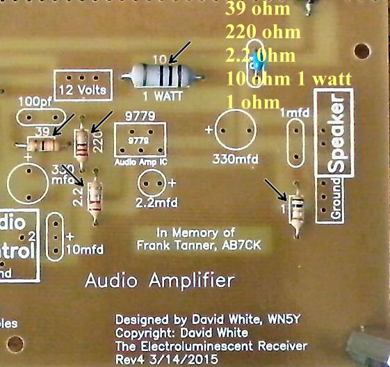
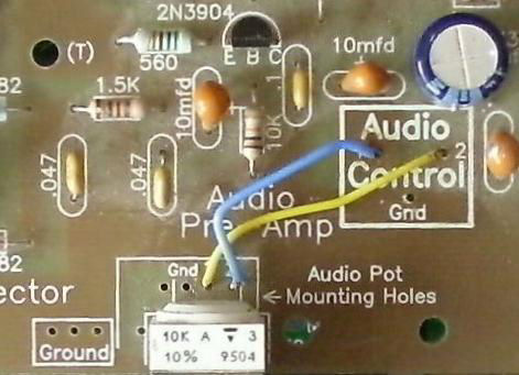
Modifications on Previous BoardsThe image below shows the mounting of the resistor and capacitor on an early Board 2. This is part of the modification as shown above done when the pre-audio amplifier was modeled in LTSpice to find the best value for maximum output with no distortion. Board 2 PCBs made after the one below has an additional footprint for the resistor and does not have to be pigtailed to the capacitor. |
|
The pre-amplifier was added to the circuit because there were some complaints the volume from the Beginner's and Experimenter's Receiver Kit was not adequate for some people and articles in ham radio literature talking about deficiencies in audio volume of homebrew receivers. In a very quiet setting of a ham shack, the "Gain Adjust" will not be needed. In high background noise environments the "Gain Adjust" cap/resistor will almost double the volume. The audio amplifier is a standard 8 watt automobile AM/FM receiver audio amplifier (TDA2002). Some kits will have a LM383, which is identical to the TDA2002. Another audio amplifier will be included in the newer kits with a house number "9779", an identical part to the TDA2002. Below is reference information from the datasheet showing the purpose of all the elements in the design of the amplifier: Most ham CW and SSB communication is between 300Hz to 3000Hz. The following is a chart made from the data of an SGS TDA2003 data sheet intended to aid the designer for fine tuning the audio amplifier. C103 and C104 were changed to 330 mfd from the recommended values of 470 mfd and 1000 mfd noted below. This was an economic decision and not related to any improvement in the circuit. No simulation was run to evaluate the changes. C106 was not included in the circuit.
My favorite speaker is a 6" with an 8 watt rating. I have found the bigger the speaker the better. The TDA2002/LM383 likes 4 ohm impedance better than 8 ohm. Both will work, but the 8 ohm will not produce as much volume as the 4 ohm. If there is considerable noise output, check the capacitors in the output filter of the product detector. If the .05 caps are bypass caps instead of .047 mono, the noise level will be very high. |
|
For additional information about the audio amplifier, check out "Audio Amplifier IC Notes", QST, August 1989, Page 41. The TDA2002 datasheet can be found at http://www.datasheetcatalog.com/datasheets_pdf/T/D/A/2/TDA2002.shtml. This is a .pdf file and requires the Adobe Acrobat Reader 4.0. Don't forget to check out "A Potpourri of Audio Amplifiers", by N1HFX. He has really good information, including a very neat IRF510 1.5 Watt audio amplifier. Also, check out "Design Guidelines for Bipolar Transistor Audio Preamplifier Circuits" for the down and dirty details. Highly recommended! |
|
|
Send E-Mail || Amateur Radio Receivers || Electroluminescent Receiver
