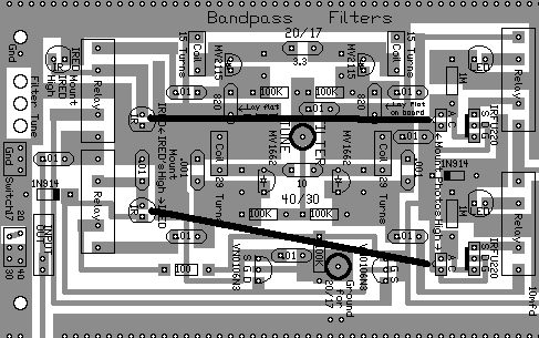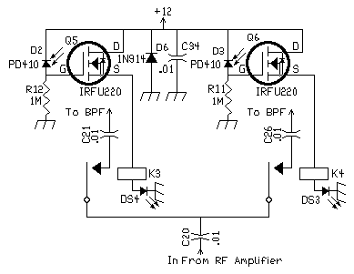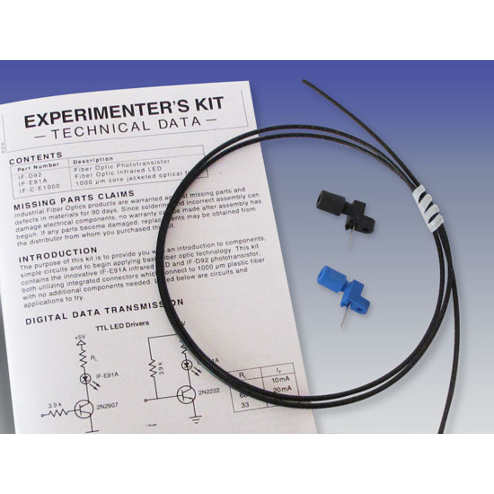


Circuit OperationThis circuit is the easiest to understand of all the IR circuits. When D2 receives IR light, the effective resistance through the photodiode decreases, raising the voltage of the gate of Q5 to turn on (above 4 volts), then the IRFU220 passes 12 Volts to the relay. In the ground circuit of the relay is an LED, which provides an indicator for which filter is on. Identical operation for D3 when IR light hits that photodiode. The 1N914 (D6) and .01 (C34) capacitor keep spikes off the relays from damaging any components. Preventing Both LEDs From Turning OnA bright light above the board will turn both LEDs/Filters on. The photodiodes have visible light filters, but they don't work well in direct sunlight or bright shop lights. To prevent an IR LED on one side from turning both LEDs on, the IR energy is blocked by the 40/30 toroids.  PhotodiodesThe photodiodes are part number PD410PI, available from BG Micro, and are high speed (200ns) types used in remote controls. They are used in high impedance circuits, and trigger high impedance gates or devices. They must be used with a MOSFET/MESFET or high impedance FET. The 1 megohm resistors, used in the gate circuits of the IRFU220's (see circuit diagram), set the impedance level for the photodiodes. The 1 megohm value worked best overall for the photodiodes, but for greater distance, resistor values have to raise a megohm at a step. In remote control applications, IR LEDs are pulsed with amps of current, which hit the photodiodes with a lot of IR energy. In this receiver, the IR LEDs are not pulsed with high current, but simply turned on. The photodiodes will not work further than about 4" to 5", without radically raising the resistor value, which makes the photodiode too sensitive to ambient light levels. Shielding the ambient light with black tubing and raising the resistor value, will yield greater distances. In the receiver applications, the photodiodes work best in short distances, and have the added value, with the visible light filter, of immunity to false triggering from shop lights. For this reason, the photodiodes/IR LEDs in the bandpass filter work fine in almost every situation and upgrading to commercial devices is unnecessary. Dividing the BoardsIf Board 1 is divided into three parts, separating the bandpass filter from next to the VFO, a commercial matched pair emitter/detector (using 1000µm optic cable) would have to be used at the IR path between the IRED (at the 20/17 filter) and the VFO 10.455 relay IR photodiode. The matched pair plug directly into the same holes. Both C's are put in the same hole. The new phototransistor has E and C terminals, whereas the diode terminals are A and C. The E and A terminals are interchangeable. No changes on the board are necessary.  |
Send E-Mail || Amateur Radio Receivers || Electroluminescent Receiver || Infrared Switching Home Page

