The roll of tape is holding up the board so all the spacers can be seen. Using the spacers
in this manner helps insert parts and provides a stable platform for soldering.
|
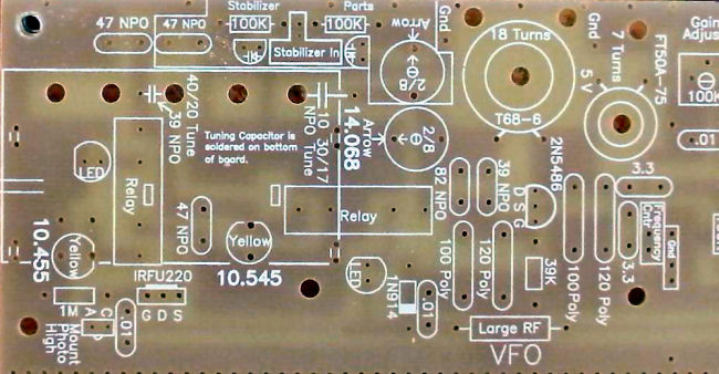
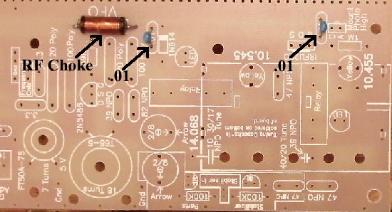
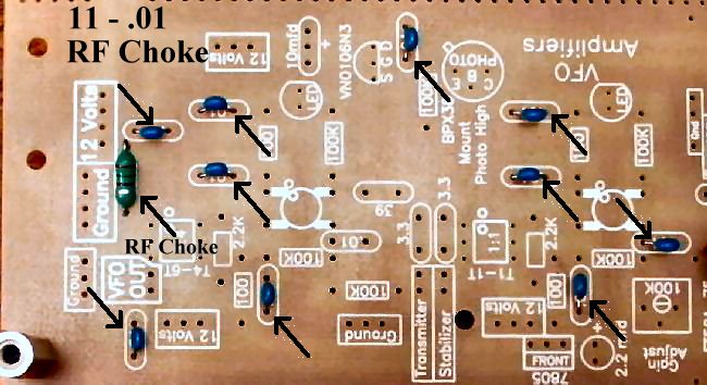
Begin each section by filling in the parts that have the value inside their footprint. They are the following: ____1 - Large RF Choke (Bag 3), Footprint on PCB is a rectangle with square edges, "Large RF" inside the rectangle. Choke is a wirewound choke about 1/2" long with black plastic ends. |
Resistors:
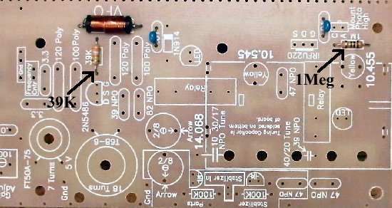
____1 - 1M (Bag 4), Next to photo diode in lower right hand corner. |
|
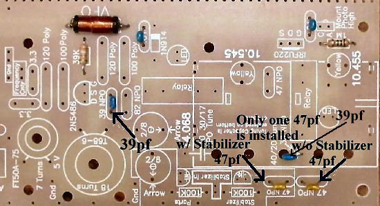
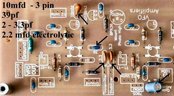
The second 39pf is located at the tuning capacitor, leave one end unsoldered until the tuning capacitor has been mounted. Bend the capacitor toward the large hole so that most of the lead length is underneath the board. The short lead will barely reach the main tuning capacitor if mounted flush with the board. Push unsoldered lead against the PCB to keep out of the way. Some kits will have one with longer leads. 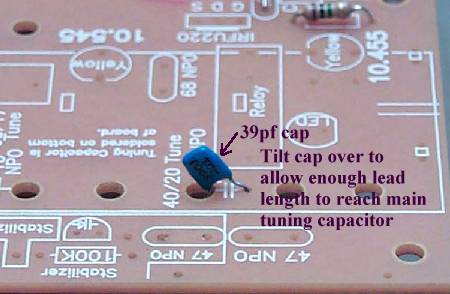 Solder
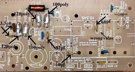
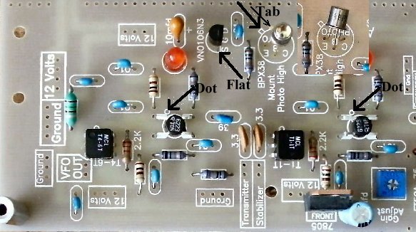
____2 - 3.3pf NPO (Bag 4), Orange colored, small square, leads flared out, labeled "3R3 D", or short leads, grey with black top, labeled "3R3" (R looks like a P). Both located next to the "Frequency Cntr" box. May be a ceramic 3.3pf in kit, note different ones in the picture. |
|
Note: Be careful not to splash solder on the Poly capacitors. Do not remove the solder if you get any on the poly caps. It will be very difficult to remove and could destroy the capacitor. Just check to make sure the solder is not touching one of the lead wires. Solder Other Parts:
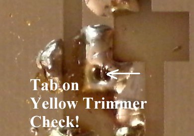
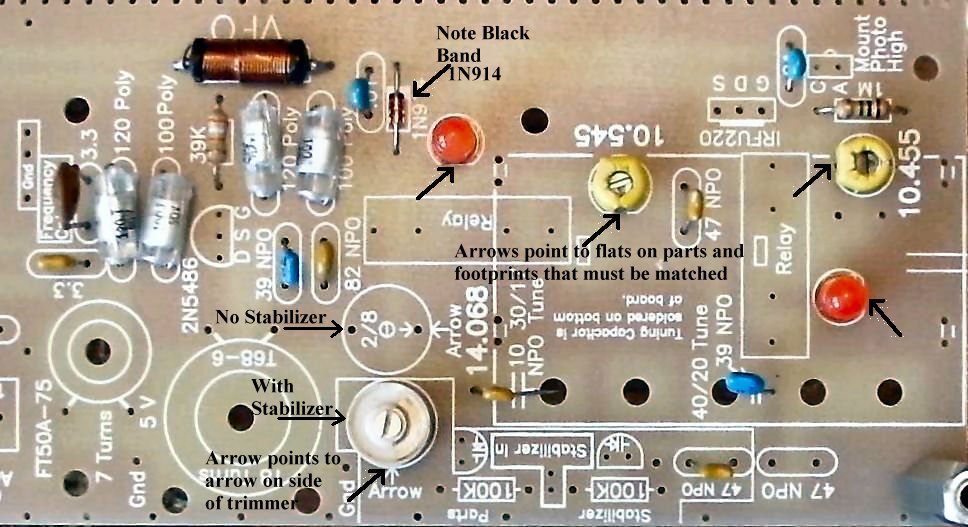
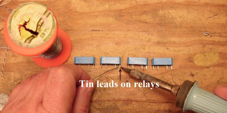
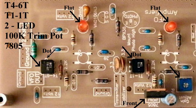
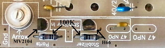
____2 - Yellow Trim caps (Bag 1), Next to relays, note flat area on body and match to the flat on the footprint.  ____1 - 2/8 Ceramic Trim cap (Bag 1), Note arrow over one leg, match the arrow on the trimmer to the arrow on the footprint. Clean and tin pins for a good connection when soldering on the board. Note: Placement depends on whether you are using the stabilizer. If you are using the stabilizer, the trimmer goes inside the stabilizer parts box as shown above and in picture below. If you are not using the stabilizer, the trimmer goes next to the 14.068 text. |
|
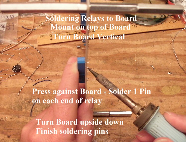
2. Be sure to mount the relays flush with the board. If mounted slightly off the board, the relay will flex back and forth while handling the board, and break the pins between the relay and PCB. |
|
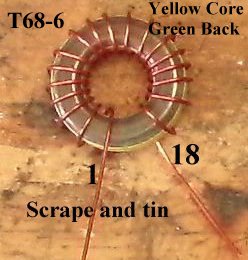
____1 - T68-6 toroid core, enameled wire (Bag 6), Pre-wound, as per instructions under the title "Preparation". Do not tie down on the board until the 14 MHz frequency has been set.
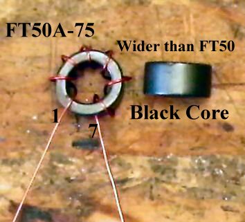
You can use a tie wrap, using the center hole and any hole around the core, or use a screw and nut with a 3/16" rubber grommet inside the toroid. (Parts not provided in kit) ____1 - FT50A-75 Ferrite Core, enameled wire (Bag 4), Pre-wound as per instructions under the title "Preparation".A small 3/16" grommet can be cut to fit inside the core, and with a 3/4" long screw and nut (4-40's), use the hole in the middle of the footprint to hold the ferrite core onto the board. (Parts not provided in kit) 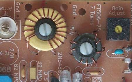 This picture shows the VFO and RF Choke held down with 4-40 nylon screws, 3/16" rubber grommet, and a metal 4-40 screw underneath the board. Solder |
|
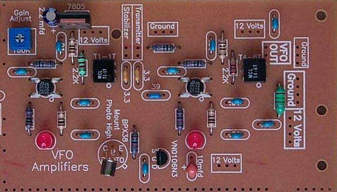
Arrows point to the dual holes and tiny rectangles that indicate where the feet of the main tuning capacitor will be soldered. Note the outline of the capacitor. The main tuning capacitor is soldered underneath the board. Small U shaped wires are placed in the holes and held down with masking tape. Then the board is turned over and the legs are soldered to the U shaped wires and the ground plane. ____1 - 5 section tuning capacitor (Bag 1), Because of its weight and size, best to mount after all the other parts have been mounted on the PCB. Information for mounting the tuning capacitor is at the end of the instructions for Board 1: First Mixer, Post-mixer Amplifier, Crystal Filters. |
|
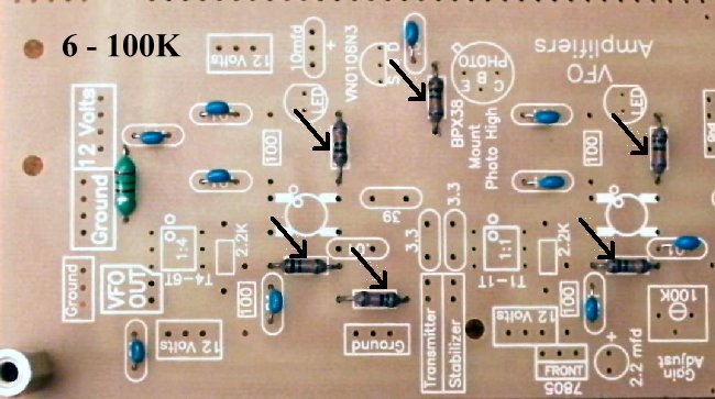
Solder ____6 - 100K resistors (Bag 3), (brown, black, yellow) |
|
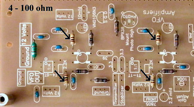
____4 - 100 ohm resistors (Bag 3), (brown, black, brown) |
|
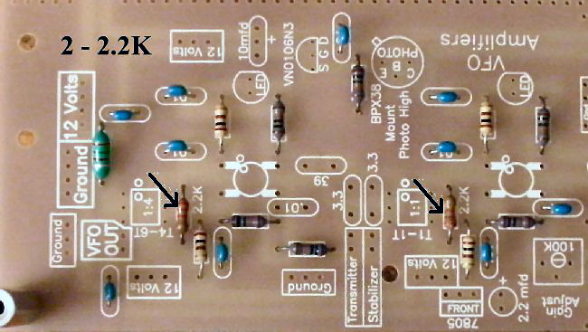
Solder Resistors:____2 - 2.2K (Bag 4), Next to the 1:1 and 1:4 transformers |
Capacitors:____1 - 39pf NPO (Bag 4), small, blue colored, short leads, labeled "390J, 201". Located at the left of the second MOSFET.  |
|
Solder Other Parts:____1 - 100K trim pot (Bag 5), located above first MOSFET, black or blue color. Turn adjustment screw all the way clockwise for the Black trimpot; all the way counterclockwise for the Blue trimpot - this gives maximum gain for initial testing and use. Black color, marked "EXP 104" on side. Blue color are smaller than the 10K blue trimmers, marked "104Fd5" on side. Note: Tin all the leads on the transformers - T4-6T and T1-1T - as the pads they solder to are small. This will make a solid solder joint. Wipe the excess solder to the top of the pin so it will fit in the holes. |
|
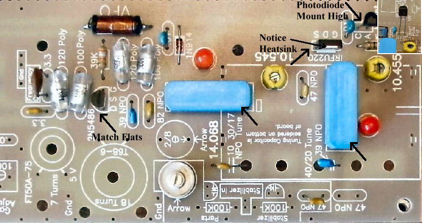
____1 - T4-6T Minicircuits transformer (Bag 4), Same notes as above, be sure to get the dot in the right place. ____2 - LEDs (Bag 3), Red color. Match flat of the LED to the flat on the footprint. Note: If you ordered the Bright Red LEDs, install them now. Do not use Super Bright LEDs here unless you change the bias resistors. See Modifying the LEDs. |
|
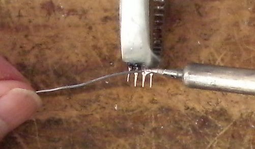
Solder  Solder ____1 - VN0106N3 (Bag 2), static sensitive part, touch a ground wire before taking it out of the bag, notice flat side of part and match the flat side on the footprint. Spread the outside leads slightly to fit the footprint. Marked "SI N, 0106, 8302".Solder ____2 - MOSFETS (Bag 2), (Picture) static sensitive part, touch a ground wire before taking it out of the bag, notice the dot on MOSFET (may be difficult to see, hold at an angle to a light source and you can see the shadow of the dot), the dot is located to the left of the second line of the text on the MOSFET. A dot is placed outside the footprint so that you can double check your placement after it has been soldered to the PCB. The leads on each side of the part need to spread apart slightly to fit the footprint. |
|
Solder Stabilizer Parts InstallationIf you are not using the stabilizer, skip this section and go to "Double Checking Your Work". ____2 - 100K resistors (Bag 3), (brown, black, yellow) Be careful: do not solder over the hole between the two resistors - this is where the output of the stabilizer connects. |
|
____Check the dot on the MOSFETs and the Minicircuits transformers. Note: If you are using the stabilizer, the adjustment screw of the 2/8 trimmer will not be grounded. ____Check the flat on the 2N5486 and make sure it matches the footprint.____Place the PCB in front of a bright light. If you see light shining through any of the soldering holes, you missed a solder connection. ____Did you remember to turn the "Gain Adjust" (1st VFO Amplifier) all the way clockwise for the Black Trimpot, or all the way counterclockwise for the Blue Trimpot? ____Make sure the front (side with lettering) of the 7805 regulator is facing towards the outside of the PCB. ____Make sure the 2.2mfd Electrolytic is mounted correctly, located next to the 7805 regulator. ____Look at all the 100 ohm (brown, black, brown) resistors and check that the size of the footprint underneath the resistor is shorter than the length of the resistor body. ____Look at all the 100K (brown, black, yellow) resistors and check that the size of the footprint is as long as the resistor body. Look for the bright yellow band to find these resistors. ____Check the tab on the BPX38 Phototransistor and make sure it matches the footprint. |
Send E-Mail || Amateur Radio Receivers || Electroluminescent Receiver || Back to Basic Instructions