To learn about the BFO and Amplifier, read the
Circuit Details - BFO/Amplifier
before building this section.
To learn about the Product Detector, read the
Circuit Details - Product Detector
before building this section.
|
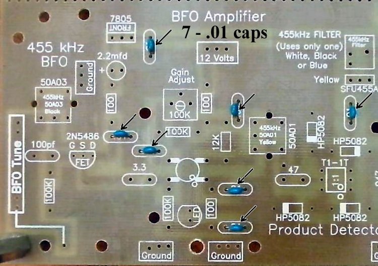
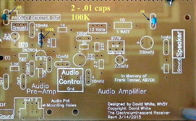
Insert all the components that have their values inside the footprint. They are the following:
____7 - .01 capacitors (Bag 3) |
|
Solder |
|
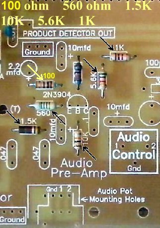
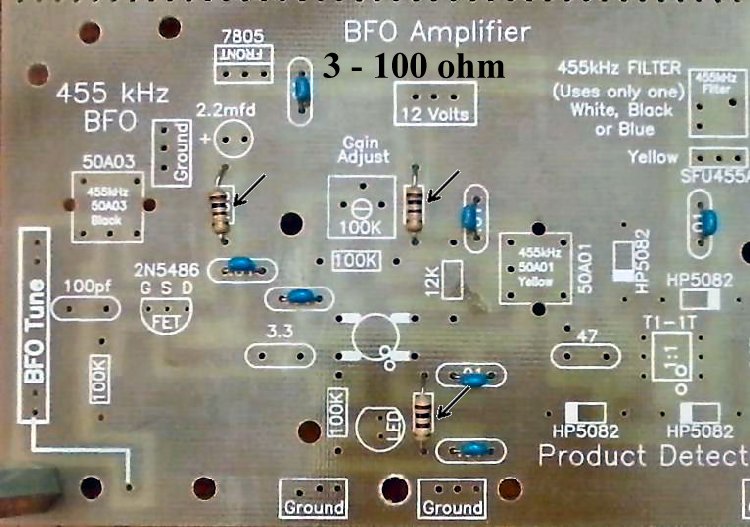
____3 - 100 ohm resistors (brown, black, brown) (Bag 3) Be careful, rectangle footprints only, there is a 100pf capacitor in the area. |
|
Solder |
|
____3 - 100K resistors (brown, black, yellow) (Bag 3) |
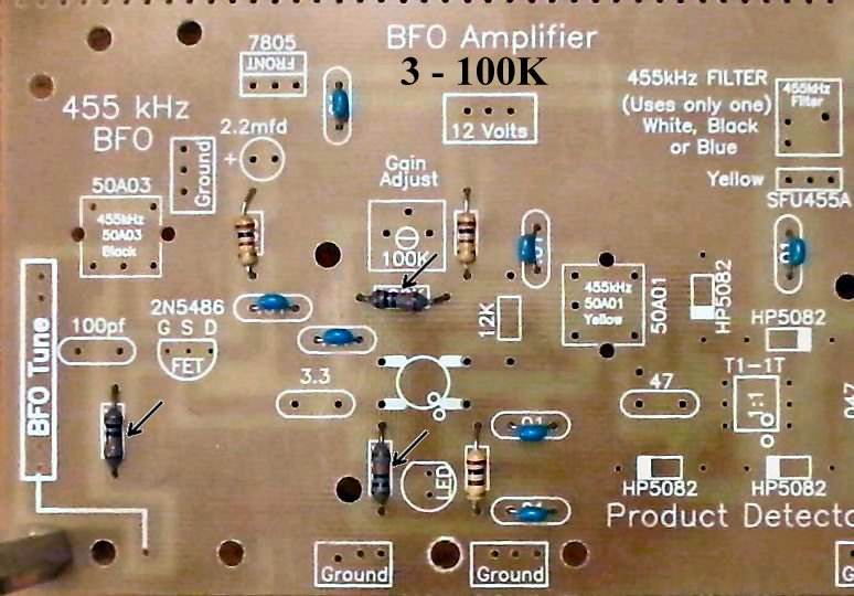
|
Solder |
Resistors:____1 - 12K (Bag 4), Located above the MOSFET on the right side. |
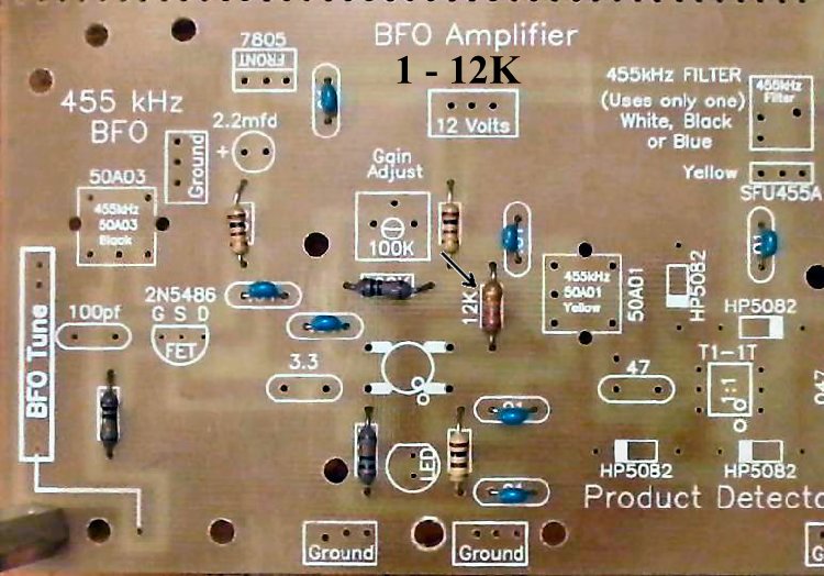
|
Solder |
Capacitors (Going left to right on the board):____1 - 100pf NPO (Bag 3), Located to the left of the 2N5486. Orange color, short leads flared out, labeled "101". |
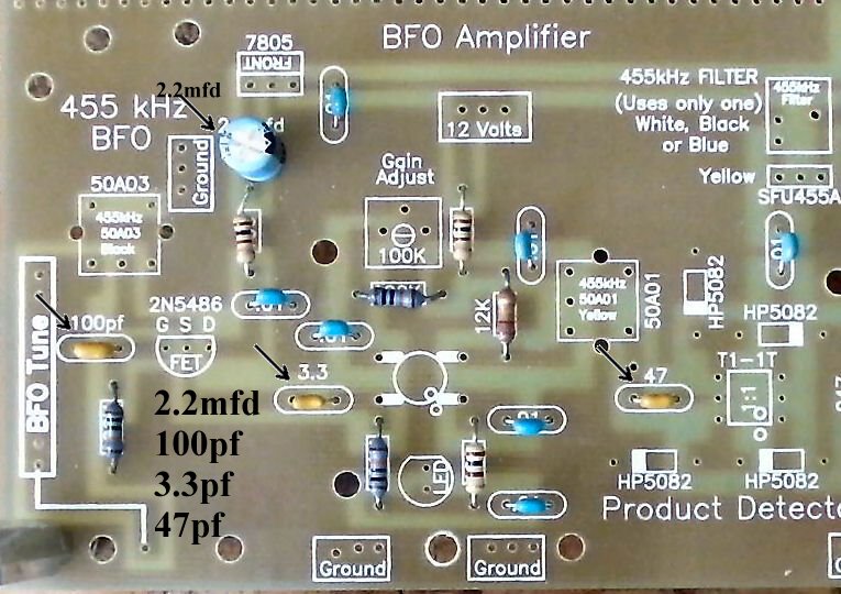
|
Solder |
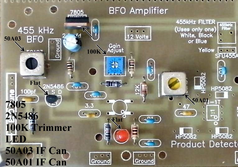
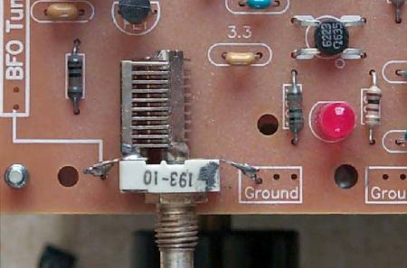
Other Parts:____1 - 50A03 455KHz IF can, Black core (Bag 6), Located below the text "455 kHz BFO". After inserting into the board, touch the soldering iron to the IF can pins first, and make sure the pin is accepting solder before flowing solder onto the PCB. |
|
Solder |
|
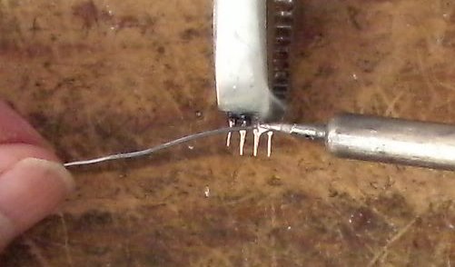
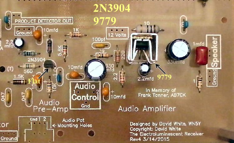
____1 - MOSFET (Bag 2), (Picture) static sensitive part, touch a ground wire before taking it out of the bag, notice the dot on MOSFET (may be difficult to see, hold at an angle to a light source and you can see the shadow of the dot), the dot is located to the left of the second line of the text on the MOSFET. Note: Tin all the leads on the transformer as the pads they solder to are small. This will make a solid solder joint. Wipe the excess solder to the top of the pin so it will fit in the holes. |
|
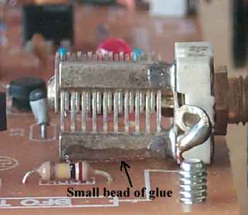
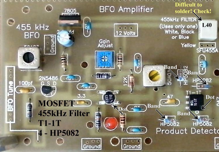
____1 - L40 B2 455KHz Filter (Bag 6), White color, another part with fragile pins, do not bend the pins when mounting/soldering the part to the PCB. Tin the leads with solder to get a good solder joint on the PCB. There are two footprints for 455KHz IF Filters, only one is used. Use the footprint that fits the pins of your part. If this part has a pin not soldered correctly, the S-Meter will show a noise level and indicate signals as you tune through a band, but no output at the speaker. |
|
Solder |
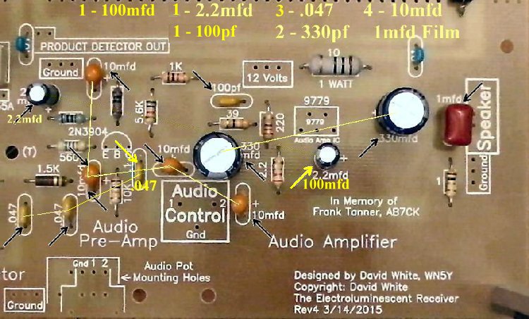
To learn about the Audio Circuit, read the
Circuit Details - Audio Amplifiers
before building this section.
|
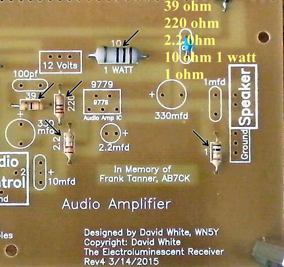
Insert all the components that have their values inside the footprint. They are the following:
____2 - .01 capacitors (Bag 3) |
|
Solder |
|
____1 - 39 ohm (Bag 5), Located above the 330mfd electrolytic. |
|
Solder |
|
Solder |
|
Solder |
|
Solder |
|
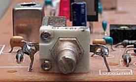
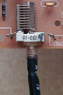
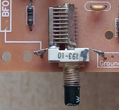
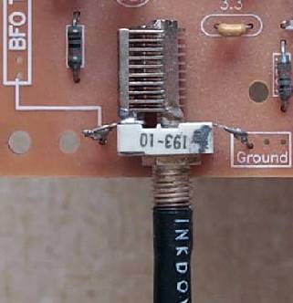
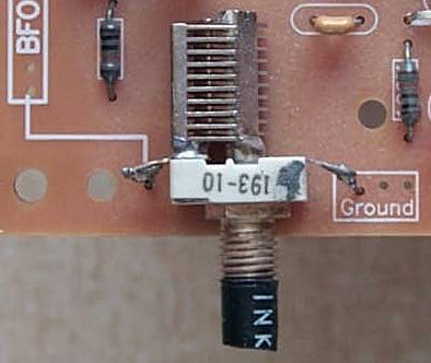
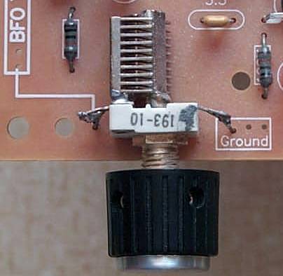
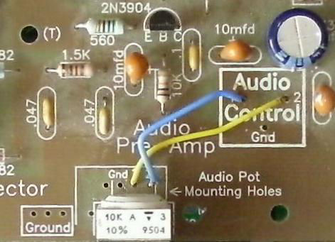
____1 - 10K Potentiometer (Bag 6), A small white pot labeled 10K in the upper left hand corner on the top. ____Use a 1 1/2" jumper wire and connect the the hole labeled "1" to the hole in the "Audio Control" square labeled "2". ____Use a 1 1/2" jumper wire and connect the hole labeled "2" in the "Audio Control" square labeled "1". S-Meter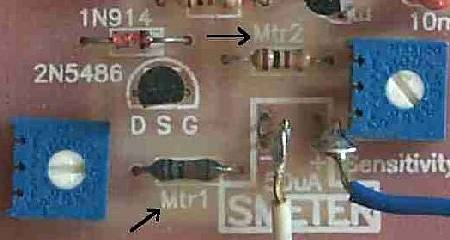 ____The resistors that are used at M1 and M2, to the left and above the S-Meter Square at the AGC Detector (Picture), are set up to use a 50uA meter. (Picture) You can use any meter with a value between 50uA to 250uA, by changing the M1 and M2 resistors. Values for different meters are given in the S-Meter page. Circuit theory is included to help you properly set up the meter any way you like. ____The S-Meter, if board mounted, is glued to the top or bottom of the board where the text "Audio Amplifier" and the "Designed by...." is located at the bottom right of the board. Silicon Rubber Sealant was used to secure the S-Meter on all the prototypes, and allows you to pull the meter off the board if you transfer the receiver to a case, where you will be mounting the S-Meter on a front panel. Picture ____Solder a wire from the + hole in the S-Meter square on the PCB to the + connection on the S-Meter.____Solder a wire from the - hole in the S-Meter square on the PCB to the - connection on the S-Meter. Picture |
Double Checking Your Work
____Place the PCB in front of a bright light. If you see light shining through any of the soldering holes, you missed a solder connection. If you have already tested Board 1, go to Mounting/Testing Board 2. |
Send E-Mail || Amateur Radio Receivers || Electroluminescent Receiver || Back to Basic Instructions