
|
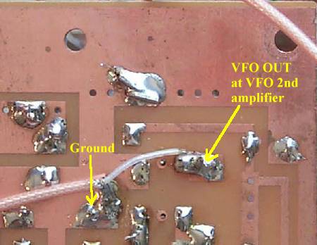
Picture shows the coax connection to the "VFO OUT" connection at the output of the second amplifier of the VFO section. Tin the braid first, saturating it with solder, cut to about 1/4" length, then solder to the ground plane. Then solder the center wire to the output pad (labeled "VFO OUT") on the topside of the board). |
|
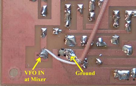
Picture shows the coax connection to the "VFO IN" connection at the input of the First Mixer. Tin the braid first, saturating it with solder, cut to about 1/4" length, then solder to the ground plane. Then solder the center wire to the output pad (labeled "VFO IN") on the topside of the board). |
|
|
Send E-Mail || Amateur Radio Receivers || Electroluminescent Receiver || Back to Basic Instructions