
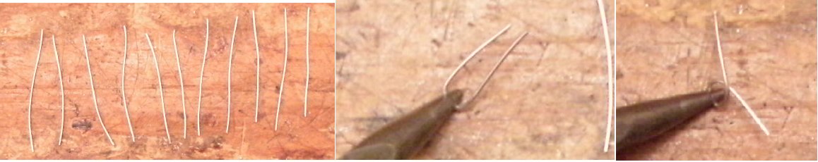
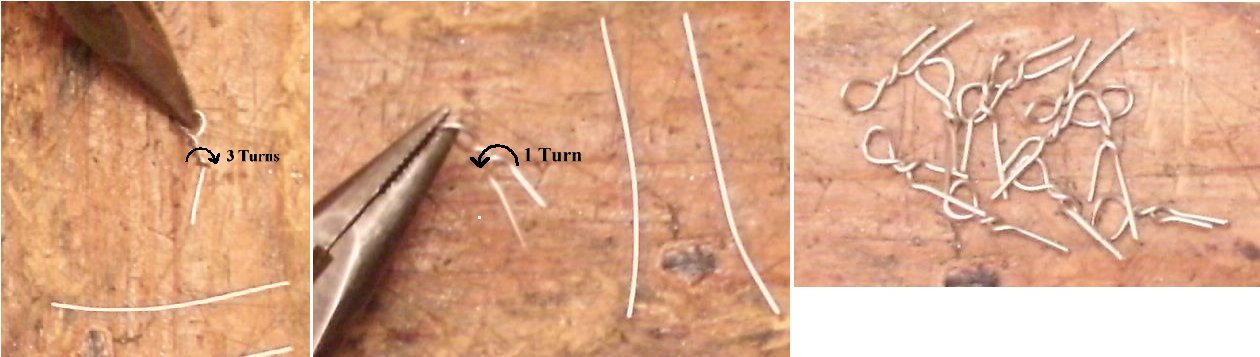
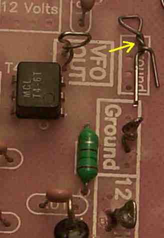
 One of the options designed into the boards is the ability to put a loop of wire at every location where a wire needs to be connected on the board. Fourteen (14) loops will be needed for both boards. The best wire to use are the clippings from the parts you just put on the board. Sort the ones out that are 1-1/4" to 1-1/2" long. If you threw away the clippings, size #22 or #20 bare wire will fit in the holes and make good stiff connections. You can strip insulated wire to get bare pieces but be careful - some insulated wire is enamel coated. 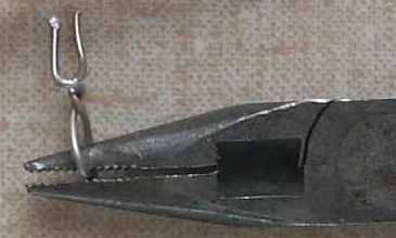 Bend a 1-1/4" or "1-1/2" length of uncoated bare wire over the end of a pair of needle nose pliers to form a loop. Give about three twists to the wire and then a half turn backward. Make 14 pieces. Using needle nose pliers makes it easy to center the wire on the pliers and holds the wire while twisting. Place the wire as close to the tip of the pliers as possible. A small loop makes it easier to solder a wire. Insert the two wires of the loop through two of the holes. Bend the wires toward the other one. Clip any excess wire length that may short to an adjacent copper trace or ground plane. Then solder the wires underneath the board. This will let you solder at will on the loops, and they will never fall out of the board. (Picture) There are four locations (8 Loops) on Board 1 and three locations (6 Loops) on Board 2 where this type of connection is very helpful in wiring the receiver. Click 'Back' on your browser to return to your previous page. |
Send E-Mail || Amateur Radio Receivers || Electroluminescent Receiver