
|
This shows the simplest way I got AM detection to work, and it was surprising how well it worked after testing other circuits.
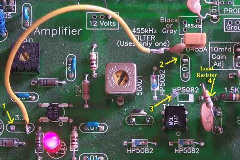
1. Remove the 3.3pf coupling capacitor between the BFO and BFO amplifier. Make sure the "Gain Adjust" pot is adjusted for maximum LED brightness. The full amplification of this amplifier is needed for good audio. If the level into the Pre-amp is too high, adjust the 50A01 transformer for best sounding audio. |
|
This AM detector comes from the article "Recent developments in circuits and techniques for high-frequency communication receivers", by Ulrich L. Rohde, KA2WEU/DJ2LR, Ham Radio, April 1980, page 20. Under the subtitle "linear detectors", Mr. Rohde explains the AM detector: "AM detectors are frequently required to have very low distortion and because of this, the IF level must be kept at a very high level. Because of gain distribution, this is not necessarily very desirable, and a feedback am detector as shown in fig. 8 is ideal." My note: This is the case with this receiver, the IF level going into the product detector is very low, -60dBm to -40dBm. To raise the level, the output from the 455 KHz filter is routed to the input of the BFO MOSFET amplifier. The 3.3pf cap is removed at the input to the BFO amplifier. Then the output of the BFO amplifier, at the 47pf cap, which is also removed, is routed to the input of this detector coupled with a .01 capacitor. Continuing with Mr. Rohde: "The output distortion is substantially less than one per cent up to a very high modulation percentages; it should be driven from an impedance of less than 200 ohms which can easily be provided by using an emitter follower." My note: The input to the detector is higher than 200 ohms, but in actual practice it seems to work fine. Fine tuning the impedance to the detector is accomplished by changing the resistor at the primary side of the transformer (50A01) in the BFO amplifier. |
|
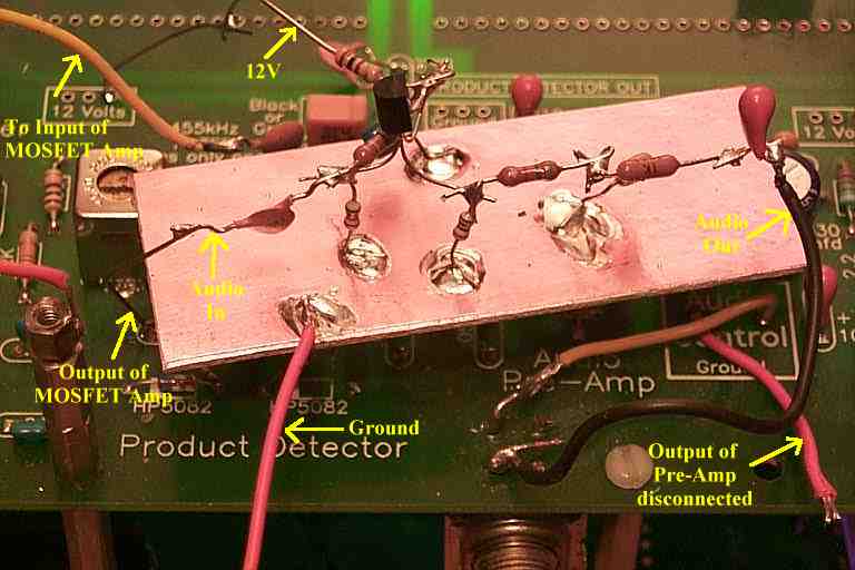
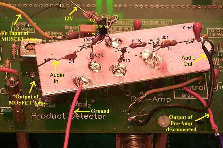
Shown above is the "dead bug" style of construction mated with the PCB board. The connection to the output of the 455 KHz filter is hidden behind the board. You can see the top of the capacitor the connects to the output of the filter. A .01 cap is used. The original one in the board is removed. The signal level from this detector will overload the Pre-amplifier, so the Audio Pre-amplifier is bypassed and not used. The output of the Audio Pre-amplifier is disconnected at the Audio Pot, and the output of the detector is put in its place. The IK resistor at the top left of the Pre-amp (going to the 12 Volt box), may be disconnected to remove power from the Pre-amp. |
|
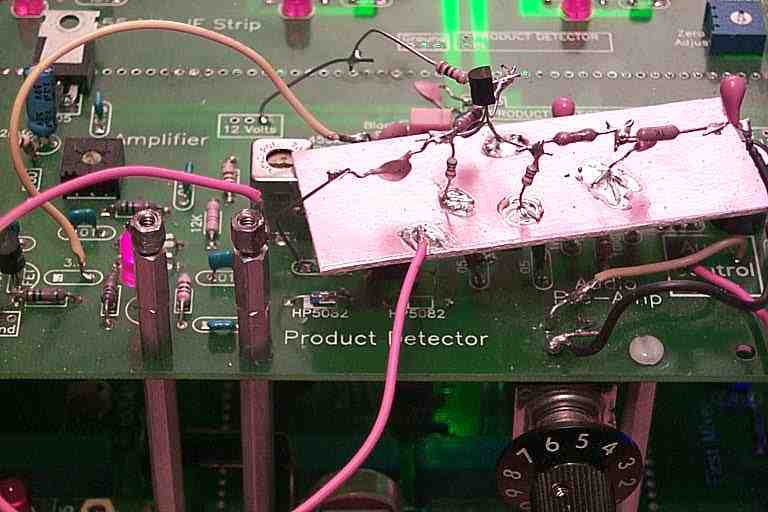
A wider angle view. Again the output of the 455 ceramic filter is hidden behind the board near the left top side. |
|
A detailed view of the audio detector construction.
|
| 1 | 2N3904 | NPN Transistor |
| 1 | 0.1 | capacitors |
| 1 | 0.01 | |
| 1 | 0.001 | |
| 1 | 10mfd | |
| 1 | 100 ohm | Resistors |
| 1 | 510 ohm | |
| 1 | 1K | |
| 1 | 5.1K | |
| 1 | 6.2K | |
| 1 | 100K | |
| 1 | Single sided PCB | Dead Bug const |
|
Low Distortion/High Dynamic Range Detector The detector provides both low distortion and very high dynamic range. It can cleanly demodulate AM signals, even with positive peak modulation in excess of 200 percent. An Improved Precision Full-wave AM Detector, by Rob Schenck, K2CU. "This circuit is a variation of the classic "Precision Half Wave Rectifier" as described in many op-amp application notes..." The Envelope Detector A mathematical analysis of the diode detector. Doug's Short Wave Radio Page Very good information on synchronous AM detection. Lots of excellent references. The Synchronous Oscillator, Designed by Vasil Uzunoglu |
Send E-Mail || Amateur Radio Receivers || Electroluminescent Receiver
