
|
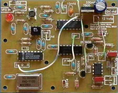
The MOSFET buffer amplifier is in the upper left hand corner of the board. The output amplifier is the CA3140. A 330 ohm resistor is the output current limiting resistor. This resistor sits next to the Varocaps output box. The 7805 regulator at the top right of the board is mounted with the front towards the outside of the board. Be very careful, installing it backwards will destroy the IC's on the PCB. |
|
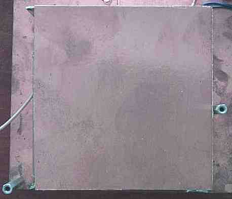
Two sides of the shield are shown above. Since the stabilizer is mounted in the back left corner, the other side shields are not absolutely needed. |
|
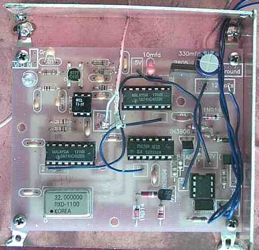
The top cover has been placed over the stabilizer PCB. Small diameter coax should be used for connections to the VFO, relay, and 12 Volts. |
Send E-Mail || Amateur Radio Receivers || Electroluminescent Receiver || Back to Frequency Stabilizer Construction