Setting the Switches for the Bands

40 Meters || 30 Meters || 20 Meters || 17 Meters

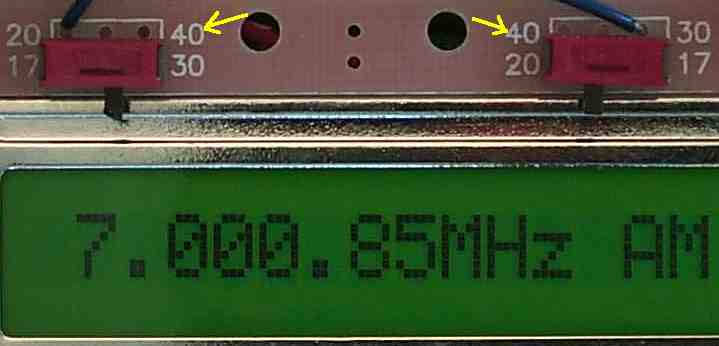
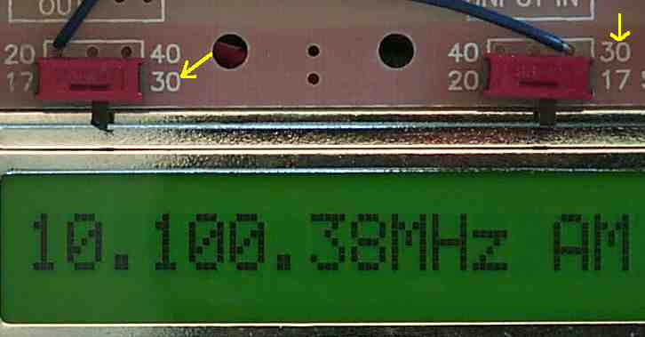
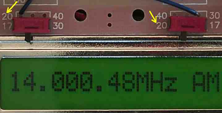
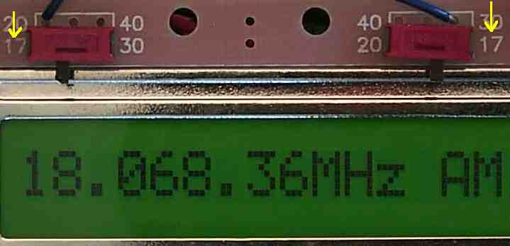
The boards shown here are an early version of the kit. The footprint for the switches are different. The currently used switches are larger and have the switch mechanism on top. The switch positions are toward the arrrows in the pictures.

The frequency counter is the AADE DFD2. This counter has been replaced by the LED 7 digit frequency counter.

40 Meters

Both Switches are toward the center.

Back to AADE DFD2 Construction - Forty Meters

Back to Mounting/Testing Board 1, Setting the VFO Frequencies

30 Meters

Both Switches are toward the right.

Back to AADE DFD2 Construction - Thirty Meters

Back to Mounting/Testing Board 1, Setting the VFO Frequencies

20 Meters

Both Switches are toward the left.

Back to AADE DFD2 Construction - Twenty Meters

Back to Mounting/Testing Board 1, Setting the VFO Frequencies

17 Meters

Both Switches are toward the outside.

Back to AADE DFD2 Construction - Seventeen Meters

Back to AADE Construction - Setting the Band and Crystal Filter Switches

Back to Tuning the Receiver

Send E-Mail || Amateur Radio Receivers || Electroluminescent Receiver || Back to DFD2 Instructions

Last Update: 10/31/09
Web Author: David White, WN5Y