
|
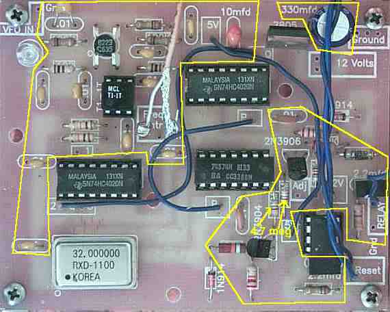
Inside the polygons are all the resistors and capacitors. A 2 meg resistor is not used, included in some kits. The 2.2 mfd capacitors around the CA3140 have been changed to 2.0 mfd. Put the two capacitors that are square and marked 205 in those locations. Use a Volt-Ohm Meter to double check resistor values. The proper placement of the 4.7 meg resistors is very important. If a lower value gets here, the stabilizer will not work.
|
|
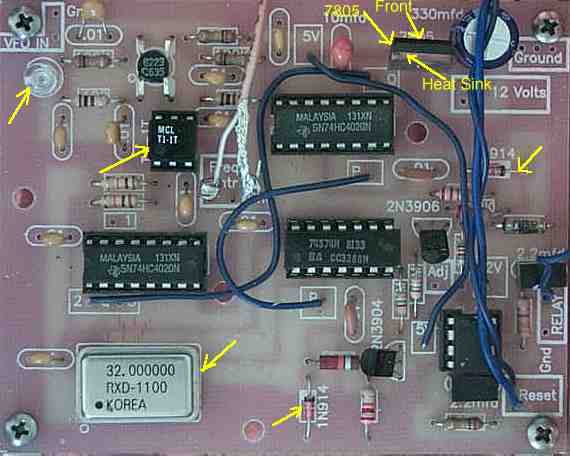
Install the 7805 regulator, two diodes, one LED, T1-1T transformer, and 32 MHz oscillator.
|
|
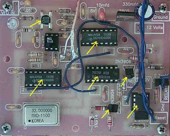
Solder the ICs, transistors, CA3140 op amp, and the MOSFET to the PCB. IC sockets are not included with the kit, but may be used if desired.
|
|
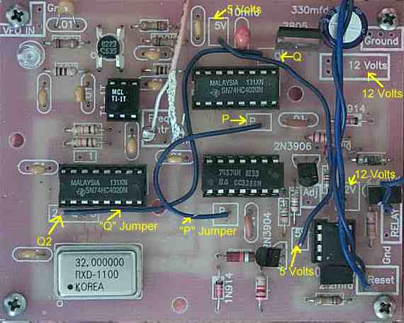
Connect wires between the "Q", the "P", 12 Volt and 5 Volt boxes. There is a wire between the 12 Volt boxes, it just got perfectly hidden by the other wires in this picture. |
Send E-Mail || Amateur Radio Receivers || Electroluminescent Receiver