
|
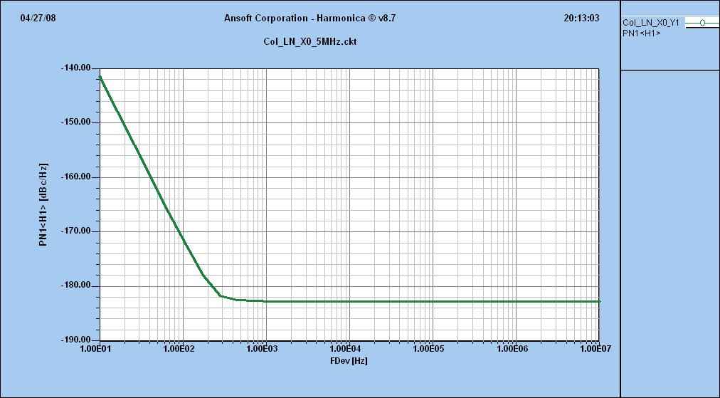
The crystal oscillator is switched in unison with the crystal filter, so that the output of the second mixer is always 455kHz. Oscillator CircuitThis oscillator is a variation of the oscillator presented by Ulrich L. Rohde, DJ2LR, in his article "Evaluating Noise Sideband Performance in Oscillators", Ham Radio, October 1978, Page 51. The original circuit is at the bottom of the web page "4 MHz Oscillator" in the Super Receiver section of this web site. I changed the output from the gate to the source because I had problems getting it to work with the output connected to the gate of the FET. The article states the above oscillator is a "suitable low-noise crystal oscillator circuit with a wideband postamplifier that delivers the required +17 dBm output level or slightly more. Any inductive-mode crystal between 400 KHz and 30 MHz can be plugged into this circuit and give useful output without any adjustments." The following quote describes the performance of the above circuit and one he shows for using third-and-fifth-overtone crystals: "The noise performance of the crystal oscillator circuits.....is better than 120 dB/Hz at 1 KHz from the carrier, and 150 dB/Hz or more at 20 KHz from the carrier. Because of their excellent noise performance, these circuits can be used as local oscillators without degrading receiver performance; very few oscillators and practically no frequency synthesizers achieve their low-noise sideband levels." Update: Email correspondence with Dr. Rohde (April 2008) shows that even better performance is now available. Dr. Rohde wrote that "...at 5 MHz my oscillator with a 2008 quality crystal, Q=2.6 E6, Cs=8ff, and some modifications gives a superb phase noise." See curve below, much better noise now. |
|
For further study, see "Technique Trims VCXO Phase Noise" by U. L. Rohde and A. K. Poddar, Microwave & RF Journal, August 2007. LED Switching of the CrystalsDiode switching is used to switch the crystal frequency. Regular LEDs were found to work just as well as 1N914s, used in almost every crystal switching circuit in Ham radio literature. The advantage of using LEDs is the visual indication of which oscillator is on, helping with diagnosis in case the switching circuit is not operating properly, or in the case of this receiver, ambient light is interfering with the proper operation of the phototransistor. If the 3.547 MHz crystal filter is on, the BPX38 does not receive any infra-red energy, and is turned off. The crystal oscillator runs at 4.000 MHz. When the BPX38 (Q1) is off, no current flows through Q1, the 100K resistor (R2), brings the gate voltage of Q2 to zero, turning off Q2. 12 Volts flows through a 1K resistor (R3), through the 3.547 crystal LED (DS2), which brings the gate of Q3 to 12 volts, which turns on Q3. No current is flowing, since the Gate of Q3 is very high impedance, so the 3.547 LED (DS2) is off. But Q3 is turned on, which supplies 12 Volts to the 4.000 LED (DS1) through a 1K resistor (R1), which yields an oscillator frequency of 4.000 MHz. If the 4.000 MHz crystal filter is on, the IRED emitter at the filter shines infra-red light on the BPX38, which turns the phototransistor on. The oscillator output is at 3.547 MHz. When the BPX38 is on, the Gate of Q2 raises to 12 volts, turning on Q2. The source of Q2 grounded, so when Q2 is turned on, the Gate of Q3 is grounded, turning off Q3, which turns off the 4.000 LED (DS1). This also grounds the cathode of the 3.547 LED (DS2) and 12 Volts flows through the 3.547 MHz LED ((DS2), turning on the oscillator to 3.547 MHz. When the kit LEDs (bright reds) are used in this circuit, there are no problems with the switching circuit. But if the LEDs are modified, a 100K resistor needs to be added to the gate of the bottom IRFU220 (One closest to the 12 Volt box near the row of holes.). This resistor goes to the gate of the IFFU220 and to the 12 Volt box. Put one lead in the middle hole of the 12 Volt box and then solder the other end to the gate lead of the IRFU220 underneath the board. See the schematic above. Tuning Oscillator FrequencyThe 200pf capacitors between the LEDs and the crystals provide tuning of the crystal frequency so that switching between the crystal filters gives approximately the same BFO note in the output of the receiver. An optional capacitor footprint is provided on the 4.000MHz crystal. Changing the 200pf caps to other values is no problem, smaller values, 5pf to 10pf, will raise the frequency and using an RF Choke, 15uH to 25uH, will lower the frequency 1 to 2 kHz. Lowering the 4 MHz crystal 1 or 2 kHz will remove a loud birdie when the 3.457 MHz crystal filter is used on 14 MHz and 28 MHz (low end). Experiments have found that the 4 MHz crysals labeled "4000 KSS 2GT(2FT)" and "4.000 ECS" are very difficult to pull. The 4 MHz crystals labeled "RXD MP49 4.000 TaiWan A7" and "EA0380J 4.000 0640A" pull up to 2 kHz. Values of over ~25uH (in series) and ~150pf (across the crystal) will kill oscillation. Molded chokes work much better than chokes wound on ferrite cores (FT37-43). Lowering frequency can be done by placing a capacitor across the crystal, a 82pf to 100pf work well for a couple of kHz. Also, RF Chokes in the 200 capacitor footprint (in series with the crystal), 15uH to 25uH can lower the frequency 1-2 kHz.Raising the frequency is done by placing lower value capacitors in the 200 capacitor footprint, 4pf to 100pf. The 200pf capacitor does very little in changing the cyrstal frequency. Optional One-crystal FilterThe four unlabeled holes on the far left hand side of the PCB picture above, at the output of the amplifier, was used for a one crystal filter to clean up the second harmonic of the oscillator. One each of the 3.547MHz and 4.000MHz crystals are installed in the holes. However, the frequency of the oscillator has to be tuned precisely so that the frequency of the oscillator is close to the series resonant frequency of the one crystal filter, so that the output of the oscillator/amplifier is not lowered a significant amount. This tuning is difficult, and was not consistent between different prototypes, so the filter was left out in the final design. Further evaluation of the circuit determined that the second harmonic of the oscillator was not degrading receiver performance. The trouble involved in tuning the oscillator frequency was deemed too troublesome. This filtering lowers the phase noise output of the oscillator/amplifier and gives an extremely clean output, but the difference was never noticed in the operation of the receiver. Improvements in the phase noise output of the VFO may give reason to improve the phase noise output of the crystal oscillator/amplifier output. The holes were left in for those that want to experiment with the filter. The horizontal traces are cut between the holes when the crystals are installed. Properly adjusted, oscilloscope tests show approximately the same output with or without the filter when the crystal frequency is set properly. Since the oscillator/amplifier drive is at a level that greatly affects the brightness of the LEDs, different levels will be easily seen. An oscilloscope is not needed, the LEDs work fine as an output indicator. The exact same crystals used in the oscillator are not needed in the filter, so any crystals with the same frequency, in the junkbox can be used. As a rule, the one crystal filter frequency is lower than the oscillator frequency. Oscillator Drive Levels and Mixer GainThe gain of the mixer is dependent on the drive level of the oscillator, and there is room for more gain, with higher oscillator output. The LED brightness of the second mixer is lower than the brightness of the LEDs at the first mixer, which is driven to its maximum when the "Gain Adjust" pot is at its maximum on the first VFO amplifier. The lower the forward voltage drop of the LED at the crystals, the greater the output of the oscillator. Replacing the LEDs with a 1N914 diode, with a .6 forward voltage drop, will raise the output level. Super Brights will lower the output considerably, with a forward voltage drop between 3 to 4 volts. The bright red LEDs have a 1.6V forward voltage drop and can be used in the circuit without a penalty in drive level. Oscillator Amplifier DiagnosisThere in nothing special in the oscillator amplifier, except the LED is brighter than the other MOSFET amplifiers in the receiver. The amplifier LED will flash when changing crystal frequencies. If the MOSFET amplifier LED does not flash when changing frequencies, there is a problem with the MOSFET circuit or the oscillator. If all the components are installed properly, and the LED does not flash, then the MOSFET will probably be bad (short between drain and source). ReferencesA low distortion crystal oscillator, that is very similar to the receiver on the internet, is at http://www.wenzel.com/pdffiles1/pdfs/xtalosc.pdf. This is a very good article to use for further study. An excellent article, "Effects of Noise in Receiving Systems", by Ulrich L. Rohde, DJ2LR, Ham Radio 1977, pp 34, has a couple of low noise VFO and crystal oscillator circuits for further study. Also check out "Stable Crystal Oscillators", by Ulrich L. Rohde, Ham Radio, June 1975, pp 34, for additional study on crystal oscillators. For every configuration of oscillators imaginable, check out "Survey of Crystal Oscillators", Roger L. Harrison, VK2ZTB, Ham Radio, March, 1976, pp 10-22. Subtitled "A comprehensive review of many circuits with recommendations to help you choose the crystal oscillator best suited to your design needs." "Evaluating noise sideband performance in oscillators", by Ulrich L. Rohde/DJ2LR, Ham Radio, October 1978, (page 51) pp. 56-7, has 2 very nice LOW NOISE crystal oscillator circuits with +17dbm output which cover 400Khz-30Mhz and 30-100 Mhz. (Article suggested by Bill, KA3AIS) |
|
|
|
|
Send E-Mail || Amateur Radio Receivers || Electroluminescent Receiver
