|
When the SPST switch (S1) is open, Q4 is on and is grounding the LEDs at the input of the 3.547 MHz crystal filter. 12 Volts goes through a 250uH choke, an LED (& 1K current limiting resistor), an IRED, (& 470 ohm current limiting resistor) and through Q4 to ground.
Also, when Q4 is on, the gate of Q5 is grounded, turning Q5 off.
When the SPST switch (S1) is closed, the gate of Q4 is grounded, turning off Q4. 12 Volts flows through the LEDs and brings the gate of Q5 to 12 volts, turning Q5 on.
Since the gate resistance is so high, on the order of megohms, no current flows and
the 3.547 MHz LEDs cannot turn on. Q5 is turned on, passing 12 Volts through
a 100 ohm resistor and 250uH choke, turning on the LEDs at the 4.000 MHz
crystal filter.
Control Center of Receiver
The IREDs at the crystal filter are the main control center of the receiver.
Operation of 40 and 20 Meters
When the 3.547 MHz crystal filter is on, the receiver is ready to receive
either 40 or 20 meters. The IRED at the 3.547 filter is on and turns on the phototransistor between the VFO amplifiers.
The 3.547 IRED pointed to the phototransistor at the VFO amplifiers turns on the 10.545 VFO relay. If the bandpass filter is switched to the 40/30 position, then 40 meters can be tuned in with the bandpass tuning pot and the VFO starts tuning at 10.545MHz. The crystal oscillator is running at 4.000 MHz, its default frequency.
If the 20/17 position on the bandpass filter switch is chosen, an IRED at the bottom of the 20 meter bandpass filter turns on a photodiode that activates the
10.455 VFO relay. The bandpass pot can now tune in 20 meters. Both LEDs at the VFO will be turned on, indicating that the VFO is running at 10.455 MHz.
Operation of 20 and 17 Meters
Switching the crystal filter to the 4.000 MHz filter will set up the
receiver to receive either 30 meters or 17 meters. The 3.547 IRED turns off, which turns off the relays at the VFO, setting the VFO frequency to 14.000 MHz.
The 4.000 IRED will turn on the phototransistor at the the crystal oscillator, changing the frequency of the oscillator to 3.547 MHz.
The bandpass filters will now tune in the 30 meter band on the 40/30
position, and 17 meters will tune in at the 20/17 position.
The 20/17 bandpass filter IRED pointed to the VFO will not turn on the 10.455 VFO relay, because the relay is not receiving any 12 Volts, since the phototransistor at the VFO amplifiers is dark (off).
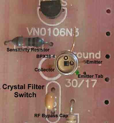
Replacing the SPST Crystal Switch with IR Switching
The phototransistor needs to be bent over, facing the front of the receiver. The phototransistor is shown straight up for clarity in showing how it is mounted.
The image shows the correct installation of the phototransistor at the Crystal Filter Switch.
The crystal filter switch is 6" to 7" from the front of the PCB, and may need more IR from the emitter, or an increase in the sensitivity of the IR receiver.
For maximum output of the IRED (50MA), use a 270 ohm, 1 watt resistor.
If the distance is going to be more than 6", best reliability will result with a 470K sensitivity resistor, and use a black tube to cover the IR path.
If covering the IR path is not done, raise the output of the IRED to it's maximum with a 270 ohm resistor.
|