|
This receiver is a beginner and experimenter's dream. Easy to build. Easy to modify. Only eight easy steps complete the receiver. Each step is fully illustrated with each group of parts highlighted for quick and accurate placement. A large prototype section is placed in the middle of the board within easy reach of all the circuit areas. This section has two 8-pin layouts and 51 4-hole foil pads. Extra five volt, twelve volt, and ground connections surround the experimenter's area. Several modifications are illustrated in the document. Get ready to learn some hands-on receiver theory! The receiver is a broadband design which can be used on any band from 20KHz to 200MHz. This is possible because all matching networks in the receiver use broadband transformers or capacitive/resistive coupling. The MMIC (Monolithic Microwave Integrated Circuit) amplifier can work from just above DC to light. The NE602's (kit may contain SA602 or SA612s) are rated to 500MHz IF's (Intermediate Frequency) and 200MHz oscillators. The Mini-Circuits T4-6T broadband transformers have a one DB insertion loss between 100KHz and 100MHz. The layout is spread out so that fingers easily reach all the components for easy insertion and changing. The silkscreen shows both the values of the parts and the reference designator. This speeds up the assembly process and helps prevent mistakes. A universal layout is used for the crystals so that any type will easily fit. The volume control is a diode attenuator placed at the output of the MMIC. The audio amplifier is a TDA2002 chosen for its simplicity, gain and low noise. The tuning range can be customized to cover an entire band or just a small segment. The bandwidth of the crystal filter can be customized by using different frequency crystals and capacitors in the ladder filter. The audio amplifier frequency response can be skewed for highs or lows by changing one capacitor. A whopping 8 (eight) watts of speaker volume is known as "arm chair copy".
INTRODUCTIONIf this is your first receiver project, build the receiver for 40 meters. Forty meters is normally filled with plenty of signals, not only ham communication, but worldwide AM broadcast stations as well. Once you have the receiver working in the 40 meter band, putting it on the other bands is very easy with only minor changes in the Input Coil and VFO circuit. Soldering technique is very important for building this kit, as soldering errors account for 99% of the problems of a newly constructed kit. Use a 30 Watt soldering iron with a small tip for best results. Keep the tip clean with a wet sponge. Clean component leads that look dirty or discolored with a knife or razor blade. Tinning the leads with solder will help considerably in making good connections. Go slowly and double check each solder joint as you go through the steps. The receiver has the best sensitivity when connected to a dipole cut to the operating frequency of interest and fed with 50 ohm coax. Any antenna will work, but at the expense of reduced signal strength. Short whips and long wire antennas used without an antenna tuner will do better with the RF Amp illustrated in the experimenter section. Strong, local broadcast AM stations can be a real problem with this receiver. Be sure to add the AM broadcast filter if you have problems of this nature. The difference will be amazing. The superheterodyne receiver was invented by Edwin Howard Armstrong during WW1, and first presented to the public in 1919. We hope that the simplicity of this kit illustrates the superheterodyne principle well enough to be easily understood by everyone and that you can share in the history and the excitement of radio.
STUFFING THE BOARDThe top silkscreen shows the value and location of all the parts. The "C" designator means capacitors and the "R" designator means resistors. The chokes (RFC), coils (L), crystals (XTAL), and IC's (U) are all marked for easy placement. Watch for the notch on one end of the NE602's and the recessed dot at pin 1 on the T4-6T broadband transformers. The diode has a black band on one end that is matched with the silkscreen. Please note that the kit may use the part number SA602 or SA612 in place of the NE602. The SA602 and SA612 are identical to the NE602.
|
|
01's - C3, C33, C31, C15, C9, C7, C10, C11, C14, C34, C19 (103) .1's - C8, C13, C29, C36 (104) .001 - C17 (102) ( ) - Indicates alternate marking for value Total Parts- 16
Lay out the mica and NPO capacitors according to value and stuff them in the board.
|
|
C30 - 220pf POLY (221) - Mount standing up with the long lead facing the NE602 (U1). This makes a handy test point for VFO frequency measurements.
C35 - See VFO winding chart for value, Step 6, Part C C32 - 85pf Variable Trimmer (Round side is ground.)
C1, C4, C5, C6 - 300pf Mica (301) ( ) - Indicates alternate marking for value Total Parts: 29
|
|
R10, R11 - 100 ohm (Brown, Black, Red) One way to make sure you are using the right value is to measure the resistors with an ohmmeter. Total Parts: 39
|
|
Diode - 1N914 - Notice correct position of the band! Please note: Electrolytics are "polarized". This means they have a "negative" and "positive" side. If the negative wire is marked, the other wire is the positive. The positive wire must be placed where the "+" mark is on the board.
C12, C21 - 2.2 mfd - Note "+" side Total Parts: 49
|
|
C2, C16 - 85pf Variable "VAR" Caps (orange) - Note flat side
and place as shown on the silkscreen.
TRAP - 10.7mhz Shielded Coil
U1, U2 - NE602'S - Note the "notch" and place as shown on
the silkscreen.
L2, L3 - T4-6T Broadband Transformers - Note the "dot" and
place as shown on the silkscreen.
3 XTALS - 10 mhz, Two for the filter, one for the BFO
U3 - TDA 2002 Audio Amplifier - Do not insert all the way
into the board, leave plenty of room for the heatsink.
Mount the heatsink first before soldering the amp to
the board.
U4 - 7805 Regulator - Note "Front" of device has part number MMIC - 1651 - Note "Long Pin", Lettering up Total Parts: 62 |
|
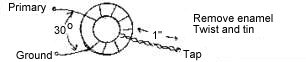
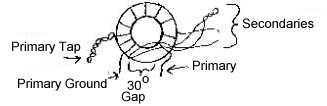
This step gives instructions for winding the two coils for the kit, the input coil and the VFO coil. Both coils use a T80-6 (or T68-6) toroid supplied with the kit. Wire size is not critical. Larger sizes (#22 - #24) are easier to handle. Sizes #20 to #28 will work. The input coil has two windings. The primary is wound first (Part A). Then the secondary is wound over the primary (Part B). The VFO coil has one winding with a tap. Instructions are in Part C. A. Input Toroid - Primary Winding
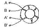
Cap Across C2 - Place across C2 on copper side of board. Install when placing the toroid on the board. Mark the primary wires with a piece of tape so they will not be confused with the secondary winding. B. Input Toroid - Secondary Winding Wind 10 bifilar turns over the primary winding - same for all the bands. 1. Take two wires, 12 inches long 2. Twist the two wires together leaving 1" leads at each end. 3. Wind twisted pair over the primary - 10 turns
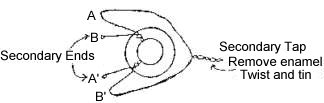
4. Trim extra lead length. Scrape the enamel from the ends (about one inch) with fine sandpaper, knife or razor blade.
5. Connect A to B', this is your secondary tap.
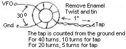
C. Wind VFO Toroid
Tap for 20 Turns, 5 Turns
*Use a 35 pf or smaller capacitor in series with the tuning cap to adjust the range to smaller values than shown in the chart.
|
|
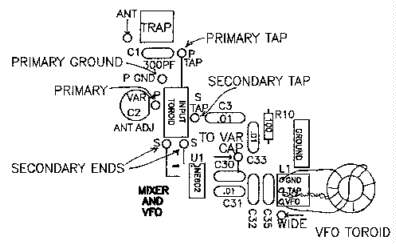
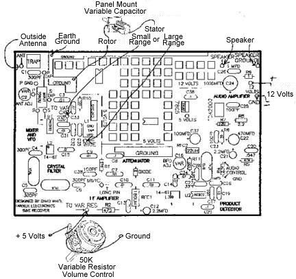
The receiver board is placed in a box with enough room left over to mount the external components. A box can be purchased, or one can be made by soldering pieces of printed circuit board together. At the very least, only the bottom, front, and rear sides are needed. The tuning capacitor and volume control are mounted on the front of the box that the receiver board is placed. The most critical is the tuning capacitor. The leads to the capacitor should be as short as possible. Use heavy wire to prevent frequency changes due to vibration or movement of the receiver box. The recommended location for the tuning capacitor is near the middle of the board close to its connection on the board. The volume control can be placed to the left of the tuning capacitor. Two components are mounted on the back of the receiver box. One is for providing power and the other is the antenna connector. Two binding posts or a RCA phono jack is mounted on the back of the box to provide a place to connect the output from a 12 volt DC (Direct Current) power supply. If you plan to use a wall plug-in power supply, check the power plug supplied and use the correct jack. For an antenna connector, use a binding post, RCA phono jack or a coax connector. The speaker can be mounted internally with the receiver or a phono jack can be used to connect an external speaker. The connector for an external speaker is usually placed on the rear of the box. An internal speaker is usually mounted on the front or top of the box. Mount the board inside the box with 1/2" to 1" metal spacers and screws. All the wires that need to go off the board are marked with an arrow for easy identification. These locations are the ANT (antenna), SPEAKER, 12 VOLTS, VAR RES (volume control), and the tuning capacitor (WIDE or VAR CAP). For best results, run a ground wire with all these components. Use the most convenient ground with your layout. Hook up all the off-board components. The volume control (VAR RES) has three leads. One of the outside leads goes to 5 volts, the other outside one goes to ground, and the middle one goes to the "VAR RES" pad on the board. If it works backwards, just reverse the outside leads. The speaker has two leads - one goes to "SPEAKER" and the other to "SPEAKER GROUND". The stator (the plates that do not move) of the variable capacitor goes to the pad on the board marked "VAR CAP" or "WIDE". "WIDE" is the recommended location for initial use and for experimenting. The rotor (the plates that move) connects to the closest ground on the board. The "ANT" on the board goes to the antenna connector. The antenna connector can be a coax connector, RCA phono jack, or a binding post. Hook up the positive lead of the power connector to the "12 VOLTS" pad on the board. The ground of the power connector should go to the closest ground on the board. Be sure to apply "+" to the "12 VOLTS" pad on the board and the "-" to ground.
TUNING THE RECEIVERTuning the receiver involves aligning the BFO (beat frequency oscillator), VFO (variable frequency oscillator), and the input toroid for the correct frequency of operation.
1. Place a jumper between the antenna input and the input to the crystal filter, which is pin 3 of L2, a T4-6T transformer. 2. Tune the "BFO ADJ" variable trimmer close to the single BFO crystal near L3, the other T4-6T transformer on the opposite side of the board. 3. If WWV is strong enough, you should hear a tone as you tune the trimmer. Zero-beat the tone and you can listen to WWV. After alignment of the VFO and front end, the tone of the background noise can be used to adjust the trimmer. 4. Set the "BFO ADJ" trimmer somewhere in between the highest and lowest tone. A simple 10MHz crystal oscillator can be used as an alignment signal, if WWV cannot be used. The test point for a frequency counter or scope is pin 7 on the NE602 (U2). The frequency should range to both sides of 10MHz. A live signal should be used for final adjustment.
The test point for a frequency counter or scope is pin 7 of U1 (NE602). 1. Remember to place the VFO tuning capacitor at full closed or open. Closed for normal tuning and open for backward tuning. (See chart in Step 6, Part C) 2. Adjustment is made by tuning the 85PF trimmer at C32. After adjusting C32, there will be some frequency drifting. This is the trimmer "setting in" and not drift from the VFO circuit. 3. Set the frequency with the value from the charts in Step 6, Part C, according to the band that you have chosen for the receiver. You will be at the low edge of the band. Moving the tuning capacitor will raise the operating frequency.
1. Trap alignment - Move the slug with an alignment tool until WWV is not heard in the output of the receiver. 2. Input toroid - Adjust the "ANT ADJ" trimmer near the input toroid until the background noise is loudest. Tune in a live signal and re-tune. The receiver is now ready to use. Further refinements can be studied in the following sections: Crystal Filter Bandwidth, Audio Amplifier, and Experimenter's Section. If you are having problems, read the following Troubleshooting section. For information on how it works, read the Theory Of Operation.
TROUBLESHOOTINGThe first thing to do is check for unsoldered pads and for solder bridges. In almost every case, this will be your problem. Touch all the components with a finger while looking at the foil side for loose wires. Check any components that feel loose. Use a small screwdriver to scrape off chunks of rosin and push on pins to make sure they are well soldered. The best place to check for solder bridges are at the components that have pins spaced .1 inch apart. Look carefully at the following parts: NE602's, L2, L3, C12, C21, C14, TDA2002, 7805 voltage regulator, and the VFO circuit (pins 6 & 7 of U1). Check a 5 volt pad for voltage. If no voltage, make sure the regulator (7805) is placed correctly on the board. Then check R10, R1, and R11 for solder bridges to ground. Make sure the back of the regulator is not touching the heat sink of the TDA2002 audio amplifier. Place a jumper between the antenna and pin 3 of L2. You should hear WWV. If not, place your finger on the plus "+" side of C21. You should hear a 60 cycle hum out of the speaker. If there is no hum, look at the audio amp circuit. With an ohmmeter, check resistors for correct values. Check the electrolytics for proper polarity ("+" side next to "+"). Always be on the lookout for solder bridges. Make sure you have an 8 ohm speaker and that it is good. If the audio amp is working and you still do not hear WWV, the places to check are the MMIC and U2. At the present time of the sunspot cycle, WWV can be received best during the day. If WWV does not work for you, use a simple 10MHz crystal oscillator for a calibration signal. Touch your finger to the input side of the MMIC (crystal filter side). If you live in a large metropolitan area, you should hear AM broadcast stations. Jumper your antenna to Pin 3 of L2, WWV should be heard. If you do not hear WWV, and the "BFO ADJ" makes no difference in the tone of the background noise, then the BFO is not working. Check oscillation by tuning a general coverage receiver to around 10MHz to find the signal or use a frequency counter at pin 7 of U2. Check for unsoldered pins at pin 6 & 7 of U2, solder bridges between the pins of U2, the BFO crystal, RFC2, and C16. Look for the notch on the NE602 and the dot on the T4-6T transformer to double check correct position. Check for 3-5 volts at pin 8 of U2 (NE602) and at the MMIC side of R1. The voltage at the ungrounded side of the diode at full volume should be zero. The "banded side" of the diode should be connected to ground. If the volume control does not work (receiver stays at full volume), look for a bad diode or RFC1 open (burned up). When the volume control is not connected, the receiver stays at full volume and there is zero voltage at the anode of the diode (opposite side from the band). If there is a loud "squealing" noise from the loudspeaker and the volume control makes little difference, replace the diode. The number on the MMIC, "1651", should be toward the crystal filter. If you are in the city with very strong AM signals, you can touch the input (crystal filter side) with your finger and hear AM broadcast stations. When C16, the "BFO ADJ" trimmer, does not produce a changing tone, and WWV can be heard, the BFO is out of range. Check for the proper value of RFC2. If the 180UH choke was placed there, the BFO will be out of range. Make sure that RFC2 is 22UH. Sometimes it is possible to mistake a choke for a resistor and vice-versa. The resistors in this kit have rounded ends, whereas the chokes have square ends. Also, the chokes have a wide silver band at one end. Double check capacitors C27 and C28 for proper values (C27-33PF, C28-15PF). The circuit is simple. If you have oscillation, you are out of range. Use the fine tuning techniques from the section "BFO ALIGNMENT". When WWV is heard, but the receiver is not working in the band you want, the problem is the circuit around U1 (NE602), or the incorrect placement of L2. Check L2, the dot should be next to pin 1. Check for voltage at pin 8 of the NE602. Using a general coverage receiver or a frequency counter, check for correct frequency and oscillation of the VFO (pin 7 - NE602). Check the windings of the input toroid. If an ohmmeter check between the primary and secondary windings shows a short, re-check your wiring. There should be no continuity between the primary and secondary windings. There should be continuity between the secondary ends and the secondary tap. If not, then the bifilar secondary wires are connected wrong. Go to Step 7 and re-check your connections. If you suspect a bad U1 (NE602), place it at U2 and see if it works there. Look closely for solder bridges underneath C32, C35, and between the pins of U1, L1, and L2.
THEORY OF OPERATIONThis receiver is a single conversion superheterodyne. In a superheterodyne receiver, the frequency of the incoming signal is "mixed" (heterodyned) to an intermediate frequency, amplified, and detected. The RF signal from the antenna is passed through an input filter. The input filter can be set for the frequency you want to receive. All other signals are then "blocked" so that they will not affect the operation of the receiver. The TRAP is used to block 10MHz signals, which would interfere with the intermediate frequency (IF) filter and amplifier. The frequency is changed in a double balanced mixer. A mixer takes two input frequencies, the RF signal from the antenna and the VFO (variable frequency oscillator), and "mixes" them to produce two other frequencies, the sum and the difference of the original frequencies. Either the sum or the difference is selected as the intermediate frequency. The NE602 is a double balanced mixer and oscillator on one chip. All the functions of the previous paragraph are done on this one chip. The RF signal, after passing through the input filter, is connected to the input of the double balanced mixer, pins 1 and 2. A tuned circuit (L1, C32, C35, & VAR CAP) is connected to the oscillator with two capacitors at pins 6 and 7. This oscillator is called the variable frequency oscillator (VFO). The VFO determines the RF signal that you will hear in the output (speaker). Since a band of frequencies is usually wanted, the VFO is made variable over a certain range. A panel mounted variable capacitor is used to change the frequency of the VFO to a frequency in the desired range. A Hartley oscillator design is used in this receiver. When the variable capacitor is connected to the VFO connection of the coil, the Hartley design allows a wide range VFO. A much smaller range is obtained when the variable capacitor is connected to the tap of the coil. The oscillator of the NE602 is internally connected to the double balanced mixer. The mixer "mixes" the RF signal and the VFO frequency, giving the sum and difference out on pins 4 and 5. Pins 4 and 5 of the NE602 are connected to a crystal filter through a broadband transformer. A two pole 10MHz crystal filter is used. Only RF signals that have been mixed to 10MHz will pass through the filter. The signal is thereby reduced in power as a result of passing through the filter. A MMIC (Monolithic Microwave Integrated Circuit) amplifier is then used to bring up signal power. The output is connected to a diode, used as a variable attenuator. This attenuator passes excess power to the ground so that the next stage of the receiver is not overloaded. A comfortable listening level is set with this control. Another broadband transformer is used to connect the output of the diode attenuator to the product detector at pins 1 & 2 of U2. A product detector, an NE602, is used to detect SSB (single sideband) and CW (morse code). The oscillator of a product detector is called a BFO (beat frequency oscillator). The BFO is a crystal oscillator. The oscillator, connected to pins 6 & 7, is changed in frequency with inductance and capacitance plus or minus 500-1500 hz. The output of the product detector is an audio frequency signal. The audio signal is output on pins 4 & 5 and is amplified by a high gain audio IC (integrated circuit) into an 8 ohm speaker.
BFO FINE TUNINGThe BFO circuit is designed to work with fundamental mode crystals up to 20MHz. The "BFO ADJ" will be more critical as you raise the frequency above 10MHz and tune broader and broader as you go down from 10MHz. C27 and C28 need to be certain values in order to give the best output for the higher frequency crystals. The formula for C27 is 100/ F. The formula for C28 is 1000/F. The capacitor values are in PF and the frequency (F) is in MHz. If a non-standard value results from the formula, use the next highest standard value capacitor. To fine tune the BFO, changing the value of C28 and RFC2 will give the best results. Move the value of C20 10PF at a time for lower values (10 to 100PF) and 50pf at a time for higher values (100 to 500PF). For low frequency crystals, RFC2 may be replaced with a wire and the capacitor used alone to pull the BFO crystal. High frequency crystals (above 9MHz) will usually always require an RF choke. Change the value of the choke 15 to 20UH at a time to fine tune its value. The rule is a capacitor will lower the crystal resonant frequency and an inductor will raise the resonant frequency. Modular RF chokes will work fine as will inductors wound on T37-2's or T37-6's.
VFO FINE TUNINGIf you are out of range, either change the value of C35 or add turns (lower frequency) or remove turns (raise frequency) from the VFO toroid. The tap does not need to be changed for minor changes in total turns. Remove or add turns at the "VFO" side of the coil. VFO maximum frequency range is 3 to 10MHz for this board. Experimentation is encouraged outside this range. Lower frequencies should be no problem. Higher frequencies are limited by the lead lengths on the board and layout. C32, C35, and C30 are used to tune the frequency of the VFO. For VFO's in the 3 or 4MHz range that are used in this version of the 40 and 20 meter receiver, greater VFO range is obtained by connecting the stator of the 35PF tuning capacitor to the VFO side of L1, marked "WIDE" on the silkscreen. In every case, a small tuning range is obtained by connecting the stator to the "VAR CAP" pad, and a large tuning range by connecting the stator to the VFO side of L1, marked "WIDE" on the silkscreen. If a general coverage receiver is used, place a short antenna lead near the VFO and tune the receiver for a signal. Adjust C32 and walk the VFO to the proper frequency. If a signal generator is used, place a short lead from the output of the generator close to the receiver. Tune C32 until the signal is found. A crystal oscillator can also be used to generate a calibration signal. For setting up a 20 meter receiver, set the generator at 14MHz and tune C32 with the VFO tuning capacitor closed. For setting up an 80 meter receiver, set the generator at 3.5MHz and tune C32 with the VFO tuning capacitor open. The circuit board is also drilled at L1 so that a shielded coil similar to the "TRAP" can be used. Shielded coils used for 10.7MHz IF's can be used for VFO's in the 5-10MHz range. This layout also accepts the L46 series of Amidon shielded coils. The L46-6 is recommended. The 85PF trimmer can be removed or replaced with a fixed value, since the slug in the coil can be used to set the frequency. If no test equipment is available, turn the trimmer at C32 a little bit at a time while peaking the "ANT ADJ" trimmer. Your tuning capacitor should be connected to the wide range pad. Tune the VFO tuning capacitor and listen to the signals. When you hear some familiar signals, you will be close to the band your looking for. Ham radio communication is unique, and should be easily picked out. Only four capacitors are needed to vary the oscillator from 3 to 6MHz, then change coil size and range from 6 to 10MHz with the same capacitors. See chart in Step 6.
FRONT END FINE TUNINGThe trap is used to prevent WWV at 10MHz from getting into the IF filter. The trap should be replaced with a wire when using crystal filters other than 10MHz. If you want to hear WWV, just place a jumper between the "ANT" and pin 3 of L2.
CRYSTAL FILTER BANDWIDTHThe crystal filter bandwidth can be changed with capacitors C4, C5, and C6. Higher values of C4, C5, and C6 give a tighter bandwidth, while lower values of C4, C5, and C6 will give a wider bandwidth. Use the same value for C4, C5, and C6. Recommended values for CW are 200 to 300PF and for SSB, 39 to 100PF. The author's experience has been that lower frequency crystals work better for CW work. Some surplus crystals in the 3 to 5MHz range have resulted in bandwidths of 300 to 700hz using 300PF caps and three pole filters. There is plenty of room in the middle of the board to experiment with different crystal filters. Higher frequency crystals (10-20MHz) work great for SSB reception and usually result in bandwidths of 2-3KHz.
SETTING THE FREQUENCY OF OPERATIONAfter selecting a set of crystals, a VFO frequency is either added to or subtracted from the crystal frequency to equal the frequency of the band of operation. For example, a 40 meter CW receiver with 4MHz crystals, use a 3MHz VFO (4MHz crystals + 3MHz VFO = 7MHz). For a 40 meter SSB receiver with 10MHz crystals, use a 3MHz VFO (10MHz crystals - 3MHz VFO = 7MHz). See the chart with the VFO winding data for other examples. The formula is expressed as follows: Crystal frequency plus or minus VFO frequency equals frequency of operation.
Xtal Freq - VFO Freq = Band Band is defined as the frequency of operation and all values are in MHz. When the VFO frequency is subtracted from the crystal frequency, remember that the VFO will tune backwards (tuning cap open for alignment at low band edge). See the following chart for an example of backward tuning (tuning cap open) and forward tuning (tuning cap closed) for alignment at low band edge.
|
|
Frequency response is changed with C26, located at the upper right side of the board. The amplifier comes stock with a 1mfd capacitor skewing for low frequencies. Most ham CW and SSB communication is between 300HZ to 3000HZ maximum. The following is a chart reprinted from the SGS data sheet intended to aid the designer for fine tuning the amplifier. |
| Part | Value | Purpose | Larger Value | Smaller Value |
| C21 | 2.2 mfd | Input DC decoupling | Noise at switch-on, switch-off | |
| C22 | 470 mfd | Ripple rejection | Degradation of SVR | |
| C25 | 0.1 mfd | Supply bypassing | Danger of oscillation | |
| C24 | 1000 mfd | Output coupling to load | Higher low frequency cutoff | |
| C26 | 0.1 mfd | Frequency stability | Danger of oscillation at high frequencies with inductive loads | |
| C23 | 39 pf | Upper frequency cutoff | Lower bandwidth | Larger bandwidth |
| R7 | 220 ohm | Setting of gain | Increase of drain current | |
| R8 | 2.2 ohm | Setting of gain and SVR | Degradation of SVR | |
| R9 | 1 ohm | Frequency stability | Danger of oscillation at high frequencies with inductive loads | |
| R6 | 39 ohm | Upper frequency cutoff | Poor high frequency attenuation | Danger of oscillation |
|
Experimenter's SectionThe front end of the NE602 is weak and has a low dynamic range. NE602's are easily overdriven by strong signals, especially megawatt AM, FM, and TV commercial stations. An AM broadcast filter is almost a necessity if you live in a large city. Also try using a battery for power as BCI (broadcast interference) can easily enter via the 110 volt wiring through a 12 volt supply. The receiver needs a resonate antenna to work best. If you're using a non-resonate long wire, a whip or an indoor antenna, an RF amplifier can help bring in the signals. An FET (field -effect transistor) grounded-gate amplifier can be used as an RF amplifier. Not much gain is wanted here because, again, you can easily overload the NE602 front end. Taping down on the output coil will decrease gain. On the higher frequency bands, you can use more gain, but the FET amplifier is more prone to oscillation. Move the tap down closer to ground on the output coil if there is trouble. A volume control can be added at R4 (right side of the BFO crystal). Remove R4 (3.3K). The pad at the bottom side (coming from the product detector) goes to the right terminal of a 10K variable panel mount resistor. The top pad (connected to C21 & R5) goes to the center terminal. Ground goes to the left terminal of the variable resistor. If the control works backwards, reverse the outside terminals. You can build the add-on circuits on the foil side of the board. Just solder directly to the pads with the receiver components on the other side out of the way. |
| Quantity | Type | Value | Ref Designators |
| Step 1/2 | |||
| 1 | Disc | .001 | C17 |
| 11 | Disc | .01 | C3, C7, C9, C10, C11, C34 |
| C14, C15, C19, C31, C33 | |||
| 4 | Disc | .1 | C8, C13, C29, C36 |
| 1 | Disc | .047 | C20 |
| 1 | NPO/Mica | 15pf | C28 |
| 1 | NPO/Mica | 47pf | C35 (40 Meters) |
| 1 | NPO/Mica | 33pf | C27 |
| 4 | Mono/Mica | 100pf | C32, C25, C38, C35-2 |
| 1 | NPO/Mica | 120pf | C35-3 |
| 2 | Polystrene | 220pf | C30, C35-4 |
| 5 | Mica/Poly | 300pf | C1, C4, C5, C6, C35-5 |
| 1 | Var Trimmer | 85pf (Orange) | C32 |
| Step 3 | |||
| 1 | 1/4 Watt | 1 Ohm | R9 |
| 1 | 1/4 Watt | 2.2 Ohm | R8 |
| 1 | 1/4 Watt | 39 Ohm | R6 |
| 2 | 1/4 Watt | 100 Ohm | R10, R11 |
| 1 | 1/4 Watt | 220 Ohm | R7 |
| 1 | 1/4 Watt | 270 Ohm | R1 |
| 1 | 1/4 Watt | 470 Ohm | R2 |
| 1 | 1/4 Watt | 3.3K | R4 |
| 1 | 1/4 Watt | 47K | R5 |
| Step 4 | |||
| 1 | 1N914 | Diode | D1 |
| 1 | RF Choke | 22uh (Small Size) | RFC2 |
| 1 | RF Choke | 180uh | RFC1 |
| 2 | Nonpolarized | 1mfd | C18, C26 |
| 2 | Electrolytic | 2.2mfd Radial | C12, C21 |
| 1 | Electrolytic | 100mfd Radial | C37 |
| 1 | Electrolytic | 470mfd Radial | C22 |
| 1 | Electrolytic | 1000mfd Radial, 10 volt | C24 |
| Step 5/6 | |||
| 2 | 6 Pin IC Socket | ||
| 2 | 8 Pin IC Socket | ||
| 1 | MMIC | 1651 | MMIC |
| 2 | SA612AN | 8 Pin IC | U1, U2 |
| 1 | 7805 | 5 Volt | U4 |
| 3 | Crystals | 10mhz | XTAL1, XTAL2 |
| 1 | 10.7mhz IF Coil | TOKO 5015-005 | Trap |
| 2 | T4-6T | 6 Pin Transformer | L2, L3 |
| 1 | TDA 2002 | Audio IC | U3 |
| 2 | Var Trimmer | 85pf (Orange) | C2, C16 |
| 2 | T80-6 Toroids | Yellow | L1, Input |
| 1 | VFO Main Cap | 35pf | Panel Mount |
| 1 | Var Resistor | 25K | Panel Mount |
| 1 | Speaker | 4 or 8 Ohm | Panel Mount |
| 1 | "U" Heat Sink | ||
| 1 | 8 Feet | Enameled wire | L1 & Pri of Input Coil |
| 2 | 3 Feet | Colored wire | Sec of Input Coil |
| 1 | 6 Feet | Hook-up wire | |
| 1 | 6-32 by 3/8" | Screw | |
| 1 | Nut | 6-32 | |
Return to: Amateur Radio Receivers ||
Beginner and Experimenter's Receiver Kit
|| Send E-Mail