

Mount Toroid Coils as Shown
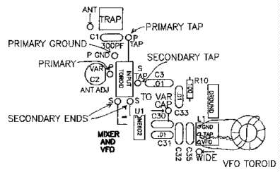
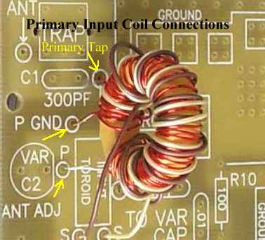
Yellow arrows point to the connections for the Input coil primary.
Remember, ground is the closest wire to the tap.
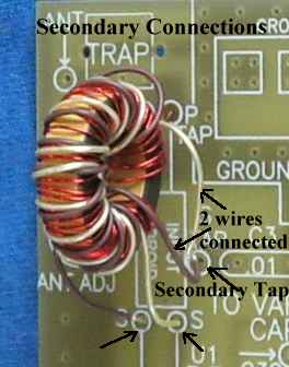
Remember again, the ground wire is the closest to the tap.
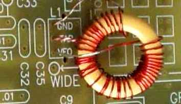
This coil should have the windings evenly spaced around the
core (with a 30 degree gap as shown) and the crossed wires
should have been fixed (about 2 o'clock).
The VFO coil should be securely mounted to avoid frequency
variations due to vibrations. An easy way is to apply wax
from a candle to hold the windings and core to the PCB.
Return to: Amateur Radio Receivers ||
Beginner and Experimenter's Receiver Kit
|| Send E-Mail