

|
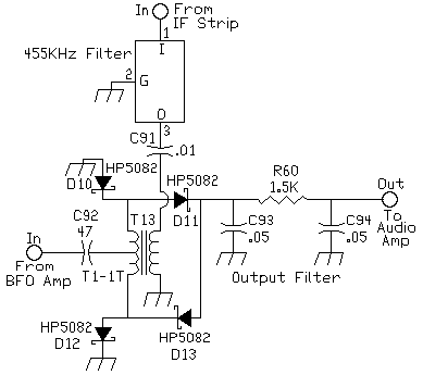
This circuit originally comes from "A High-Performance Receiver for 160 Meters", Solid State Design for the Radio Amateur, by Wes Hayward and Doug DeMaw, p. 136. The diode product detector was the easiest to build and gave the lowest noise output. Standard 1N914 diodes work perfect in this circuit. The Schotky diodes shown in the schematic give slightly more output due to their lower forward voltage drop. The output of the 455 kHz IF strip is fairly high, so a high gain product detector does not work well here. Also, the noise of the receiver is considerably lower with a diode product detector over an active product detector. T13 is a ferrite core (FT50-43) with a trifilar winding of 10 turns with #22 wire. Wire size is not critical. The 455 kHz filter is a ceramic filter (Murata SFU455A) with a 10 khz bandwidth at 3dB. It helps lower the noise output of the IF strip. Any inexpensive 455 kHz filter will work here. The filter can be left out if one can't be found. |
 Send E-Mail || Amateur Radio Receivers || Super Receiver || Super Receiver Circuit Details
