

|
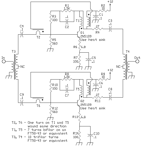
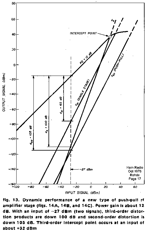
This amplifier comes from the article "Optimum Design for High-frequency Communications Receivers", by Ulrich L. Rohde, DJ2LR, Ham Radio, October 1976, page 10, fig 14A. As stated in the article, Page 21, "...uses voltage and current feedback to minimize intermodulation distortion, while the transformers act as impedance stabilizing devices." The input and output tranformers are trifilars wound with 10 turns on FT50-43's. Impedance ratio is 1:4. The transformers on the 2N5109's are built as shown in the diagram. Wind the 1 turn loop in the same direction as the rest of the winding. I used FT50-43 cores. Recommended cores from the article are Indiana General F625-0-TC9 for 1.5-30 MHz or F625-9-Q1 for higher frequencies. I had no trouble getting this circuit to work. I built it "dead Bug" or "ground plane" style with a shield placed between the two amplifiers. I don't know if the shield was necessary. I ran the 12 Volts lines against the ground plane to high megohm (22M) resistor standoffs. Shown below is a chart showing the dynamic performance of this amplifier. Power gain is about 12 dB. 
Can i buy doxycycline online ukPurchase doxycycline online uk or if you prefer to check the online pharmacy of drugstore.com. We provide all the FDA required information according to our Terms and Conditions. The link for uk medication is http://ukprescriptiononline.eu/doxycycline/online-purchase-doxycycline. This drug |