
|
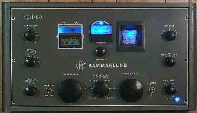
This receiver is my ultimate homebrew receiver in which I use the circuits that are supposed to give the best performance. All the circuits are built "dead bug" style. The receiver is a 20 meter CW receiver, which is my favorite band and mode. The Super Receiver is built into a Hammarlund HQ-140X. The case and chassis have plenty of room and an original fantastic VFO dial. The dial is the main reason I picked this case for the receiver, as it has absolutely no backlash and is very smooth to tune. The is very important because of the narrow bandwidth of the crystal filters. The main limitation of receivers with very narrow bandwidths is the ability to tune them. Since this receiver is using a discrete VFO that is tuned with a variable capacitor, a very solid drive is needed to enjoy the narrow bandwidth of the filters. Receivers using DDS or PLL technology may not have this problem, but I have not gotten that far with my VFO projects. The recent installation of a Vacker VFO and a "Huff and Puff" stabilizer is extremely stable and is much easier to build than the DDS or PLL VFOs. Manhattan construction is another way to build the circuits. For an example of this technique used in building a transceiver, check out K8IQY's 2N2/40 Homepage.  Image Map Block Diagram of ReceiverReceiver Circuit Details
The 2N5109 Amplifiers
Humorous Article on this Receiver Image Map Block Diagram of ReceiverReceiver Circuit Details
The 2N5109 Amplifiers
Humorous Article on this Receiver
|
Return to: Amateur Radio Receivers
|| Send E-Mail
