|
The following procedure has resulted in excellent performance of the stabilizer. Most tests have indicated stability within + or - 1Hz stability. The only difficulty is removing the 47pf capacitor after the main tuning capacitor has been installed. Do not remove the main tuning capacitor if you have problems with the 47pf cap. You can burn off the capacitor from its leads and add a new one. Email me if you need a capacitor or help. See instructions below. |
|
Varicaps are inserted between the ground end of the 8pf ceramic trimmer and the 47pf NPO capacitor next to the 10.455 relay. Either a MV2104 or a H66 (a 50pf varicap) can be used at the 8pf trimmer. All the new stabilizer kits will have one MV2104 and one H66. The MV2104 is used at the 8pf trimmer and the H66 is used with the 47pf NPO capacitor. Readjustment of the toroid windings will be necessary to get the 8pf trimmer in the 14 MHz range of the VFO. The addition of the varicap will raise the 14 MHz frequency and bringing the windings closer together will be necessary. When lifting the 8pf ceramic trimmer, place it at an angle where it can be adjusted easily. Then use plenty of melted wax to secure the trimmer and connections so they do not vibrate or move when adjusted. The cathodes of the varicaps are soldered to the capacitor and the anodes are soldered to ground. A 100K resistor is soldered to the junction of the capacior/trimmer and the varicap. The other ends of the 100K resistors are tied together and then wired to the output of the stabilizer (marked "Relay"). See the pictures below for details: 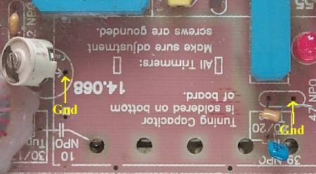 Unsolder the ground end of the 8pf ceramic trimmer and the 47pf NPO capacitor. Be very careful with the 47pf cap - it is very fragile. Remove the solder on the bottom side of the board first. Do not pull on the capacitor while applying heat or the lead will come out of the capacitor. Use needle nose pliers to grab on the lead rather than the body of the capacitor. 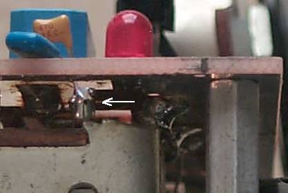 If you are retrofitting a built receiver the picture above shows the location of the ground lead of the 47pf capacitor between the tuning capacitor and the PCB. The lead can be reached with a long, narrow soldering tip. Or by clamping needle nose pliers on the top of the lead, heat the lead on top of the board until it unsolders. If you cannot reach the bottom ground of the 47pf capacitor, you can burn the cap of its leads and solder in a new one. See below: 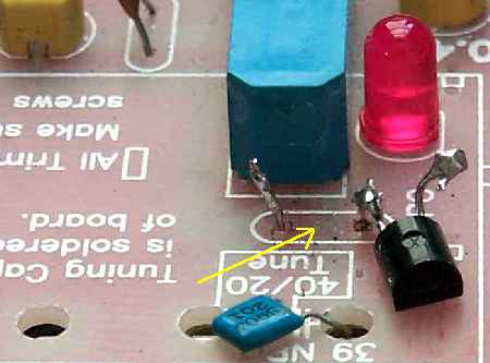 The yellow arrow points to the footprint of the 47pf capacitor that has been burned off its leads. Place the soldering iron tip on the capacitor body. The capacitor will begin to melt. Then pull up with the tip and the capacitor will come off its leads. 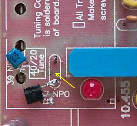 Then solder the anode of the 50pf varicap to the ground side of the capacitor - bottom lead in the picture above. 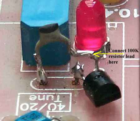 Next, solder a new 47pf capacitor to the cathode of the varicap and the top lead. The arrow points to the connection where a 100K resistor lead will be soldered. 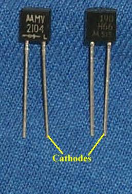 The H66 varicaps do not have a symbol on them indicating the anode/cathode of the part. Use the above picture to locate the correct pins. The pin pattern for the H66 is the same as the MV2104. |
|
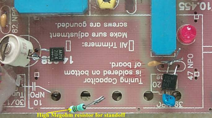
Solder the varicaps between the trimmer/capacitor and the original ground connection. Be sure you have the cathode connecting to the trimmer/capacitor. Solder a high megohm (equal or greater than 2 megohm) resistor to the ground connection shown on the board. This will provide a standoff to solder the 100K resistors from the varicaps. |
|
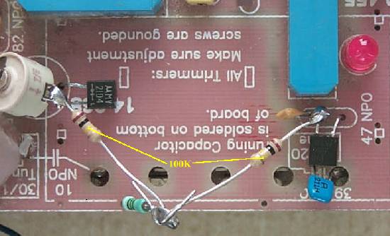
Solder the 100K resistors to the junction of the varicap and trimmer/capacitor. A high megohm (above 2 meg) 1/4 watt resistor is mounted in a ground hole near the edge of the board to provide support for the other ends of the resistors and a tie point for the wire going to the output of the stabilizer. |
|
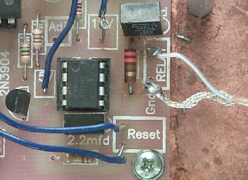
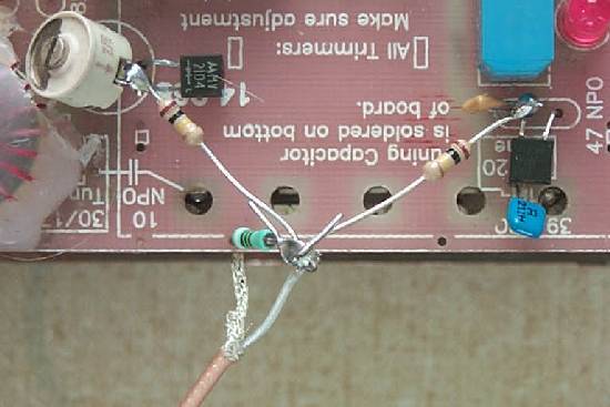
The output of the stabilizer is marked "Relay". Connect the cable to the stabilizer first. If the connection on the PCB is made first it is difficult to get to this connection. Note the ground and center wire connections. There is a "Gnd" label next to the Ground hole. Or solder the shield underneath the board on the ground plane. |
|
Connect the center wire to the 100K resistor junction. Solder the shield to the ground plane underneath the PCB. After the PCB is mounted back on the spacers, melt some wax over the ceramic trimmer and over the 47pf capacitor to keep them from vibrating. The wax gives support to the ceramic trimmer so adjustments can be easily made. Check to me sure you have easy access to the trimmer with an adjustment tool before you wax it down. Adjustments to the ceramic trimmer will need to be made with an insulated tool. The trimmer adjustment screw is no longer grounded.
Drugstore lip liner uk
Tab Fluconazole 150 Mg Price
90-100 stars based on
562 reviews
Diflucan is used for treating and preventing certain yeast and fungal infections. Fluconazole pharmacy australia Phone: +61 7 3389 4500, toll-free, 8am - 8pm AUS time Website: http://www.fda-sa.gov.au/about-us/contact-information/drug-information-maintenance-consumers/consumers-contacting-fda/ Consumers looking to contact the manufacturer of a particular medicine in Australia should visit the manufacturer's website. Please ask your pharmacist about the latest information available. Consumers searching for information on any medicine listed drugstore lip liner uk below should contact: Manufacturer (name of or producer) Pharmacist National Contact Point National Contact Point website on the of Pharmaceutical Benefits Advisory Committee Please contact the manufacturer immediately if you are not satisfied with the care or quality of prescribed medicine. If you cannot find the information are looking for or you have an enquiry complaint, can contact the following: Pharmacy Benefits Pharmacy Benefits website: www.pharmacybenefits.gov.au Pharmacy Benefits on Twitter @PharmacyBenefits Pharmacy Benefits on Facebook Australian Therapeutic Goods Administration Telephone: (03) 9344 2222, Australia wide Website: http://www.atsda.gov.au/ To report suspected illegal importation of medicines, or provide any information related to illegal importation, you may call the following services or visit website of the ATSB, or visit an Australian Food and Drug Administration ( AFFA ) or Therapeutic Goods Administration ( TGA ) authorised facility or visit the website of each body. If you have any questions about this website you can contact: Australasian Poison Control Centre Tel: 1800 332 000, Australiawide Email: apccininfo@aph.gov.au Website: http://www.aph.gov.au/ You can also contact: Australian Food and Drug Administration Telephone: 03 9530 1557 Website: http://www.fda.gov.au/ Telephone: (00) 03 9629 7200 Website: http://www.tga.gov.au/ Australian Therapeutic Goods Agency Telephone: (03) 9344 3100, Australia wide Website: www.tga.gov.au/ Other medicines may be listed on Pharmaceutical Benefits Scheme Medicare Register. You may also find our Fluconazol 120 Pills 1mg $345 - $2.88 Per pill complete list of Medicines approved for use in Australia at the Therapeutic Goods List website. Australian Government and Health Insurance Ombudsman Ph: 1300 364 277 The Australian Government and Health Insurance Ombudsman website http://www.hiaok.gov.au/ has all of your questions answered on complaints about Commonwealth and State government programs, which include Medicare, Aged Care, Child Support, Family Tax Benefit, Workcover, Personal Accident and Sickness, Disability Support Pension, etc. Australian Government and Health Insurance Ombudsman web site http://www.hiaok.gov.au/ also acts as a government intermediary, mediator and referral centre in relation to problems with health insurance coverage or payment.
generic fluconazole price fluconazole tablet usp 150 mg price fluconazole uk pharmacy fluconazole online pharmacy fluconazole the generics pharmacy online pharmacy for fluconazole Fluconazol 30 Pills $302 - $275 Per pill Fluconazole 150 mg tablet cost $16.10 and 100 mg tablet cost $17.30. For a $50 savings the drug was not worth cost, but for a $250 savings the were more than four times that amount. As the cost of drugs continued to go up, the average monthly drug cost increased to $38.78, which is Buy diclofenac sodium an increase of more than 33% between 2009 and 2011. Cynthia Plante, president of the Academy Oncology management, said she agrees that "when we are talking about treatment of cancer, the savings are significant and they going to be even online pharmacy fluconazole greater over time." For example, in 2011-2012, every $100 saved by reducing the cost of drug treatments by one percent, the cost was reduced by approximately $13.45. However, Plante said that a $500 savings is not enough to justify the additional drug cost. "At $250 per month, then if you can only save $500 per month, then it's only worth it if you can save in the neighborhood of $2,000 a month," said Plante. According to the Academy of Oncology management, cost cancer drugs How much does over the counter viagra cost has increased at a rate of 5% per year for the last eight years, and a 5% increase in the cost of drugs at end 2011 will put the total increase in cancer drug prices for 2012 at 2.6%. The cost of most commonly used cancer drugs, tamoxifen and aromatase inhibitors, increased at a rate of 6.1% in 2011-2012 and will increase by 3.3% in 2012. The average cost of most commonly used cancer drugs increased by 10.7% over the past six years.
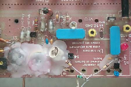 Picture shows the wax applied to the ferrite choke, VFO coil, 8pf ceramic trimmer, and the 47pf capacitor. This provides a firm mounting and a stable VFO. Trim wax off the top of the ceramic trimmer before it cools or anywhere else to prevent damage to the parts. |
|
____Start with the resistors and capacitors. Picture You will not install a 2 meg resistor that will be left over in some kits. Be sure to get the 4.7K in the right footprint. If it gets in a 4.7 meg spot, the integrator will not work. Be careful mounting the 7805. The front of the 7805 faces to the outside of the board. The bold line of the footprint indicates the location of the heat sink, the back of the 7805. Be sure to get good solid solder joints at the pins of the regulator to the PCB. ____Install the 7805 regulator, two diodes, one LED, T1-1T transformer, and 32 MHz oscillator. Picture____Solder the ICs, transistors, CA3140 op amp, and the MOSFET to the PCB. A pin on the ICs is easily missed, especially one of the c |