|
The interface to the receiver has gone through three different designs: Magnetic Coupling || Varicaps Placed on the Tuning Capacitor
Varicaps in Series with Trimmer/Adjustment Capacitors New Rev2 Boards Integrate Parts on PCB
|
|
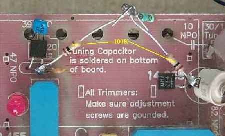
The second interface replaced the relay with MV2104 varicaps mounted on the main tuning capacitor. The MV2104's have worked very well. The construction technique is explained at Stabilization using Varicaps on the Main Tuning Capacitor Two varicaps and two 100k resistors are mounted on the main tuning capacitor. The mounting is done on the tab side with round holes. The 100K resistors are connected to the cathodes of the varicaps and tied together on the other end to connect to the frequency stabilizer output. 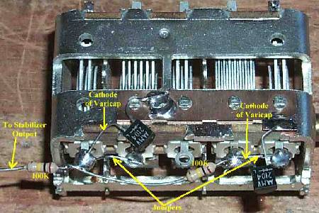 Note in the picture above that the cathode of the varicaps is attached to the stator of the capacitor. The two end sections of the main tuning cap are tied together for more capacitance. A jumper wire is used to tie the sections together. They are only tied together on this side. The connections to the stator on the other side of the capacitor are used to connect to the VFO. The output of the stabilizer (labeled relay on the stabilizer board) is connected to the two 100K resistors. One disadvantage of this technique is that the range of the stabilizer varies according to the placement of the main tuning capacitor. When the main tuning capacitor is at full capacitance, the range of the stabilizer is only 1-4 kHz, while at minimum capacitance is 50-60 kHz. Another disadvantage were the modifications to the VFO and tuning capacitor. A higher value coupling cap in the 14 MHz VFO was needed and sections of the tuning capacitor were tied together. These modifications were easy, but it changed all the stock settings and ranges. The effect of the MV2104's would be very little at the maximum capacitance of the capacitor but would be considerable at the minimum capacitance setting. The result is too little stabilization at the maximum setting and too much at the minimum setting. Be aware that the capacitor value used in this kit is rather large (200pf). In other VFOs where the tuning capacitor is smaller, the varicaps tied to the tuning capacitor may work fine over the entire range.
|
|
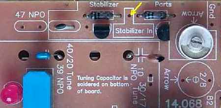
Note that C83 (6.8 pf NPO) at the 40/20 tune circuitry has been added in series with the MV2104. The reason is the MV2104 only has about a 10-12pf capacitance. Putting the MV2104 on the 47pf cap would raise the frequency of the 40/20 VFO out of range. With the 6.8pf and the MV2104 only a minor readjustment of frequency is needed. For retrofitting early kits, there should be an extra 6.8pf or 10pf capacitor after building. Either the 10pf or 6.8pf will work. I would expect that any value from 6.8pf to 15pf would work at C83. At the 30/17 tune circuitry, the MV2104 is larger than the 8pf trimmer capacitor and does not move the 14 MHz VFO out of range of the trimmer. The VFO coil windings should be raised to 19 turns, but by squeezing the windings together, an 18 turn VFO coil can be made to work. |
Reset Button and ShieldingThe Reset Button is used to set the stabilizer back to the middle of its operating range. The stabilizer should be reset after the first five minutes of turning on the receiver and then about every couple hours afterward. A shield Picture is used between the tuning cap and the stabilizer. Ideally, the stabilizer should be completely shielded with feed-through caps for power and coax cable to the relay and to the VFO output. |
|
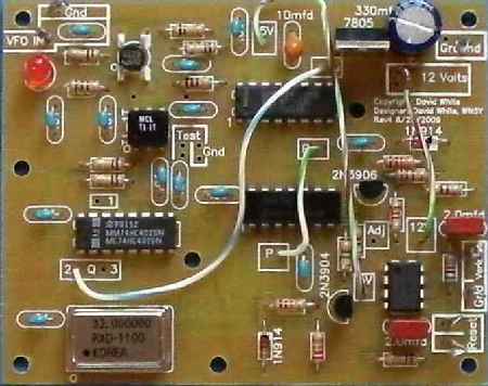
The input buffer/amplifier (upper left hand corner) is the same MOSFET amplifier that is used in the receiver. This gives a very high impedance input so that the output of the VFO is not affected. The crystal oscillator (bottom left) runs at 32 MHz. A CA3140 op amp (bottom right) is used as the output device for this stabilizer. The box labeled "Relay" is the output of the stabilizer. Both the output and ground holes are in the box. The Ground connection is labeled "Gnd" next to the box. |
|
This stabilizer can also be used in different receivers with different frequency VFOs. The only change that will have to be made is at the "Q" connection at the first 74HC4020. For lower frequency VFOs (under 10MHz), use the "Q1" connection at pin 15 of the 4020. For frequencies higher than 14MHz, use the "Q3" connection at pin 2 of the 4020. This rule is not cast in stone. Experiment with different division outputs of the 4020 until you find the best division pin. See the schematic for which pins to use. Back to Stabilizer Construction |
|
This stabilizer circuit evolved from the stabilizer circuit in the February 1996 issue of QEX, "Frequency Stabilization of L-C Oscillators", by Klaas Spaargaren, PA0KSB. For understanding circuit operation check out this article and the others listed below at Hans Summer's web site. The only change I made in the output to work with the relay was to change the output resistor on pin 8 of the CA3140 from 10K to 330 ohms. (Reference diagram is from Klaas' article above.) The other changes were using 4020's instead of the 4060's, and an IC crystal oscillator (32 MHz) replaced the discrete transistor oscillator. Connection changes were made between the first and second 4020's (pin 1 to 11 instead of 6 to 11) to adapt to the kit's higher frequencies. I also added a very high impedance MOSFET input amp. The output of this amplifier drives the stabilizer. The "Freq Cntr" box is not used. It was intended to drive a Frequency Counter but the output was too high and overloaded the input to the counter. ReferencesFor further reading and understanding of the circuit, please go to Hans Summer's web site and look up the following articles: "'Stay Put' The Improved Huff & Puff VFO", by Chas F. Fletcher, G3DXZ, Radio Communication, December 1997 (file name rcdec97as.gif). This article gives all the troubleshooting, formulas, and theory on the operation of his stabilizer. The stabilizer used in the kit is a variation of his design, and all his formulas and troubleshooting apply. A must read if you want to understand this circuit. Technical Topics, Rad Com, July, 1996 (file name ttjul96as.gif). The circuit in this article is very close to the one used in the kit. The differences are that the kit uses a crystal oscillator can at 32 MHz, rather than a discrete oscillator running at 48MHz, and uses 4020's instead of 4060's. This article also gives excellent information on theory and troubleshooting. The second page of this article is extremely useful at helping to pinpoint a problem with the stabilizer. The circuit diagram contains errors. "Frequency Stabilization of L-C Oscillators", by Klaas Spaargaren, QEX, February 1996, pp 19-23. This circuit diagram was noted for its lack of errors, and the inventor describes his improved version of the stabilizer. Another complete article that explains circuit theory and troubleshooting. This same circuit is explored in the Technical Topics article above. The kit's stabilizer evolved from this circuit. "Waveform Conversion, Part I - Sine to Square", Alternate input circuits for the stabilizer. Circuits to convert RF sine wave inputs to square wave for use in the stabilizer. Be sure to check out Hans' magnetic coupled stabilizer. |
Send E-Mail || Amateur Radio Receivers || Electroluminescent Receiver || Frequency Stabilizer Construction